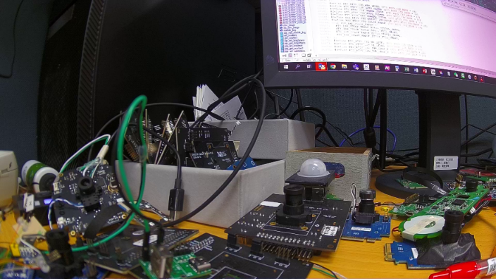
[AmebaPro2] Introduction for Switch flow(Day / Night mode)
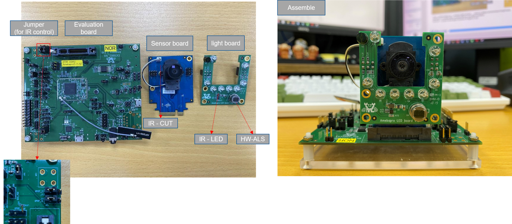
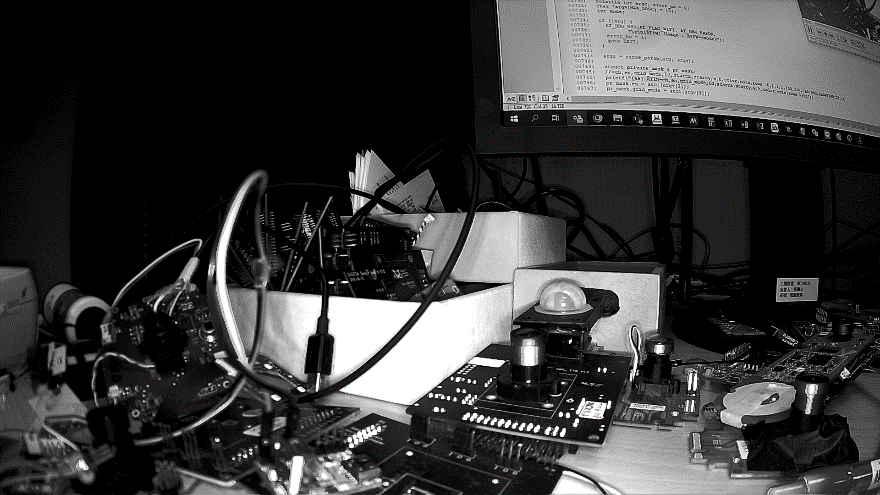
EVK of AmebaPro2
*ALS = abbreviation for「ambient light sensor」, used to detect environment brightness
*IR-LED = un-visible light, compensate for low light condition
*IR-CUT = control cover glass (remove IR light or not)
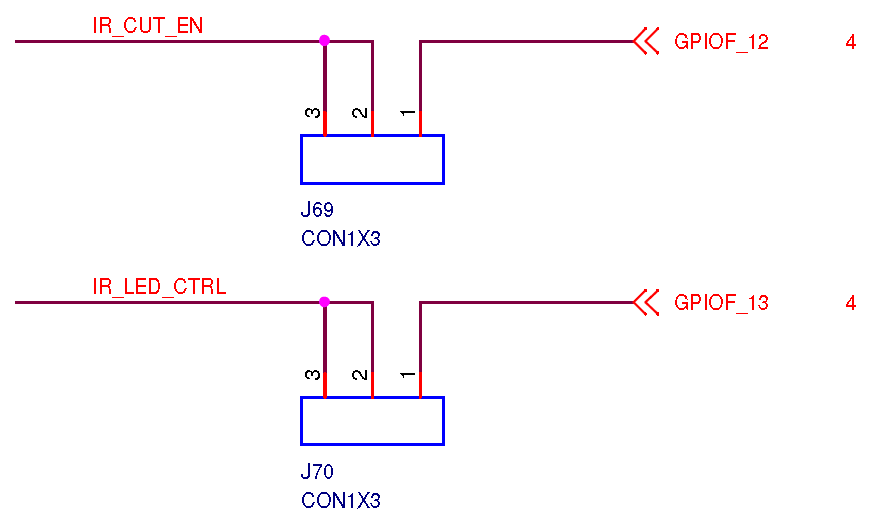
Pin define for IR control
IR-CUT: single GPIO
IR-LED: PWM
Initialization for IR control
Pin assignment
Ref to 「ir_cut.h」 and 「ir_ctrl.h」
Initialization and enable function
Ref to 「ir_cut.c」 and 「ir_cut.c」
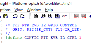
How to enable IR control
Ref to 「Platform_opts.h」
Ref to 「Video_example_media_framework.c」

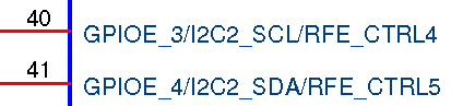
Pin define for HW-ALS control
Through sensor board interface
HW-ALS: i2c type
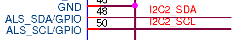
Initialization for HW-ALS control
Pin assignment
Ref to 「Ambient_light_sensor.h」
Initialization and enable function
Ref to 「Ambient_light_sensor.c」
How to enable HW-ALS control
Ref to 「Atcmd_isp.c」
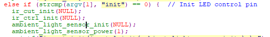
Command: ATIR=init
Should notice that not to initialize IR control twice
General flow of day/night mode switch
Switch to 「Day Mode」
Disable IR LED
Keep IR Filter
Set ISP to Day Mode Parameter
Set ISP to Color Mode
Switch to 「Night Mode」
Set ISP to Gray Mode
Remove IR Filter
Enable IR LED
Set ISP to IR Mode Parameter
Refer to 「mmf2_video_example_v1_day_night_change_init.c」
This example shows how to set 「IR control」 / 「 ISP 」 / 「 Motion detection 」 configuration during mode switch
Switch between both mode without reference to ALS value
General flow of day/night mode switch
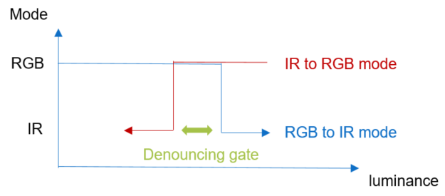
Criteria for changing mode
Criteria to switch between 「Day mode」 and 「Night mode」
Refer to Ambient light sensor data
HW
Through i2c / spi to communicate with sensor
RTK EVK use I2C type HW-ALS
Detect for luminance strength
Same trends to environment luminance
SW
Through ISP information
Detection for luminance strength, compensate for it
Opposite from trends to environment luminance
Bright scene |
Dark scene |
|
|---|---|---|
HW ALS value |
↑ |
↓ |
SW ALS value |
↓ |
↑ |
How to use 「HW-ALS 」to active mode change flow
How to active 「HW-ALS」
Use video example to apply streaming
Ex: mmf2_video_example_v1_init()
Reference code
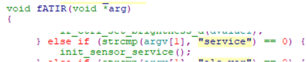
Atcmd_isp.c
ATIR=service
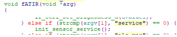
Should initialize IR control before apply sensor_service
Reference code
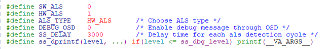
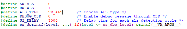
sensor_service.c
Select ALS_Type
HW-ALS setting
threshold for mode switch
Reference control flow
「sensor_thread」
How to use 「SW-ALS 」to active mode change flow
How to active 「SW-ALS」
Use video example to apply streaming
Ex: mmf2_video_example_v1_init()
Reference code
Atcmd_isp.c
ATIR=service
Should initialize IR control before apply sensor_service
Reference code
sensor_service.c
Select ALS_Type
SW-ALS setting

Reference control flow
「sensor_thread」
How to Get SW-ALS Value
Based on ISP AE Statistic Information
Exposure Time
isp_get_exposure_time()
Gain
isp_get_ae_gain()
These information both are based on IQ configuration such as AE metering, AE target and stable flow
For Example
10ms Exposure time with 5xGain (Bright condition)
ALS Value = 100 * 5 = 500
60ms Exposure time with 33.75xGain (Dark condition)
ALS Value = 600 * 33.75 = 20250
Refer to ISP_Get_ETGAIN()
How to active SW-ALS in amebaPro2
Debug command
ATIR=getlight
Get sw-lux value
ATIR=als_ver
Get SW-ALS algorithm version
ATIR=dbg_als,level (level = 0 ~ 3)
Enable debug log in als algorithm
ATIR=dbg_ss,level (level = 0 ~ 1)
Enable debug log in sensor service thread
1: print ALS value & stable information
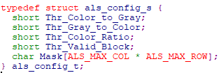
Introduction for SW-ALS parameter
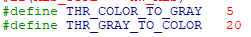
ALS THR from RGB Mode to IR Mode
Thr_Color_to_Gray
ALS THR from IR Mode to RGB Mode
Thr_Gray_to_Color
Color ratio to check whether visible light is enough
Thr_Color_Ratio
This value will be lower when visible light is enough
Full IR LED: more close to 256
Strong visible light: lower than 192
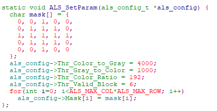
Mask with Thr_Valid_Block
Adjust for detection ROI and valid block
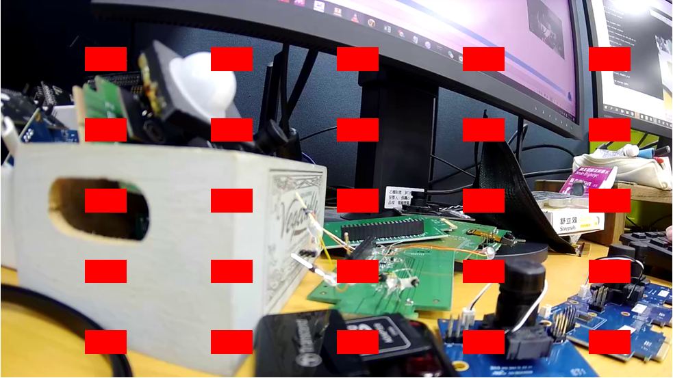
Default parameter (For Circle ring IR LED replacement)
Center counting with maximum detection block = 13
Valid Block = 6
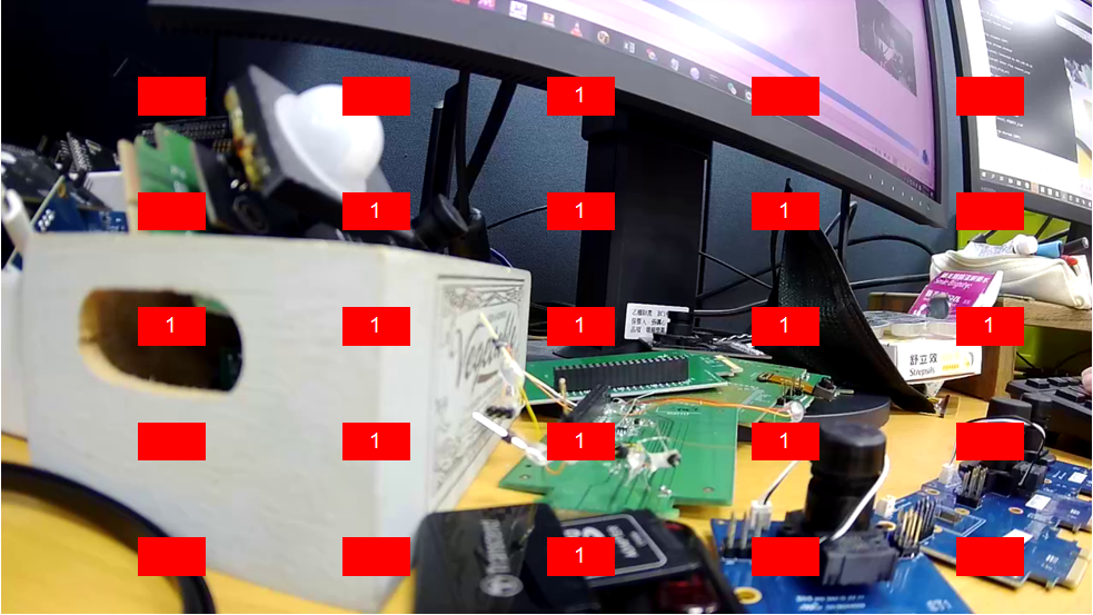
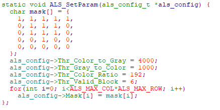
For IR LED is replaced in bottom of the DUT
Detection in top of frame with maximum block = 12
Valid Block = 6

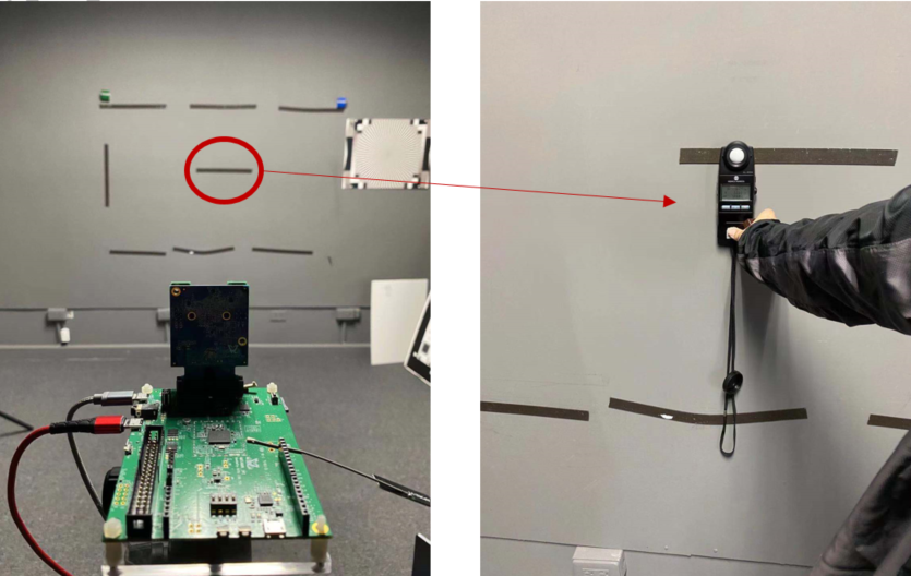
SW_ALS Tuning
Test Condition
Target: 18% gray wall
Distance: 3m
Measurement: 3m from camera module
Set Environment Luminance to Dark Level (EX: 3 lux)
@Day Mode
THR_COLOR_TO_GRAY
Set Environment Luminance to Bright Level (Ex: 8 lux)
@IR Mode
THR_GRAY_TO_COLOR
Use ALS debug mode
ATIR=dbg_als,2
In most case default value would be available
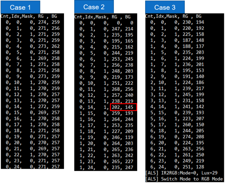
Case 1: No visible light with IR LED
Case 2: few visible light with IR LED
check some ref value is lower than Thr_Color_Ratio
Case 3: Enough visible light with IR LED
Fit switch criteria and change mode to RGB
Date |
Version |
A uthor |
Release note |
|---|---|---|---|
2023.04.14 |
1.0 |
Zako Wu |
Draft version for customer release |
2023.06.27 |
2.0 |
Zako Wu |
Update ALS algorithm for version 2.0 |
2024.10.30 |
2.1 |
Zako |
Add flow to active sw-als |