IQ Manual Calibration
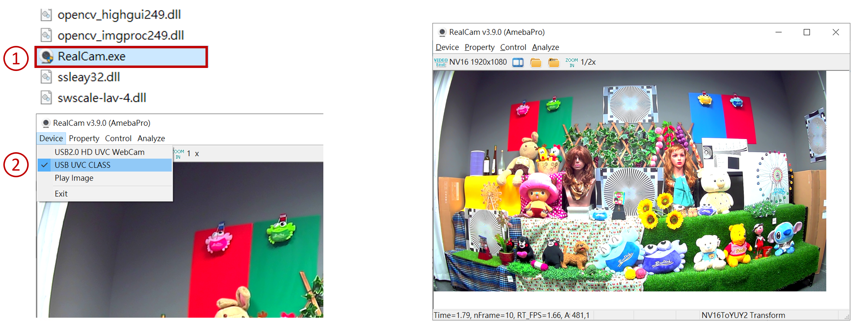
Preview video stream via RealCam
RealCam does not support Windows 7, please use Windows 10.
NV16toYUY2 and NV12toYUY2 need to be registered first.
Basic Calibration Module
BLC
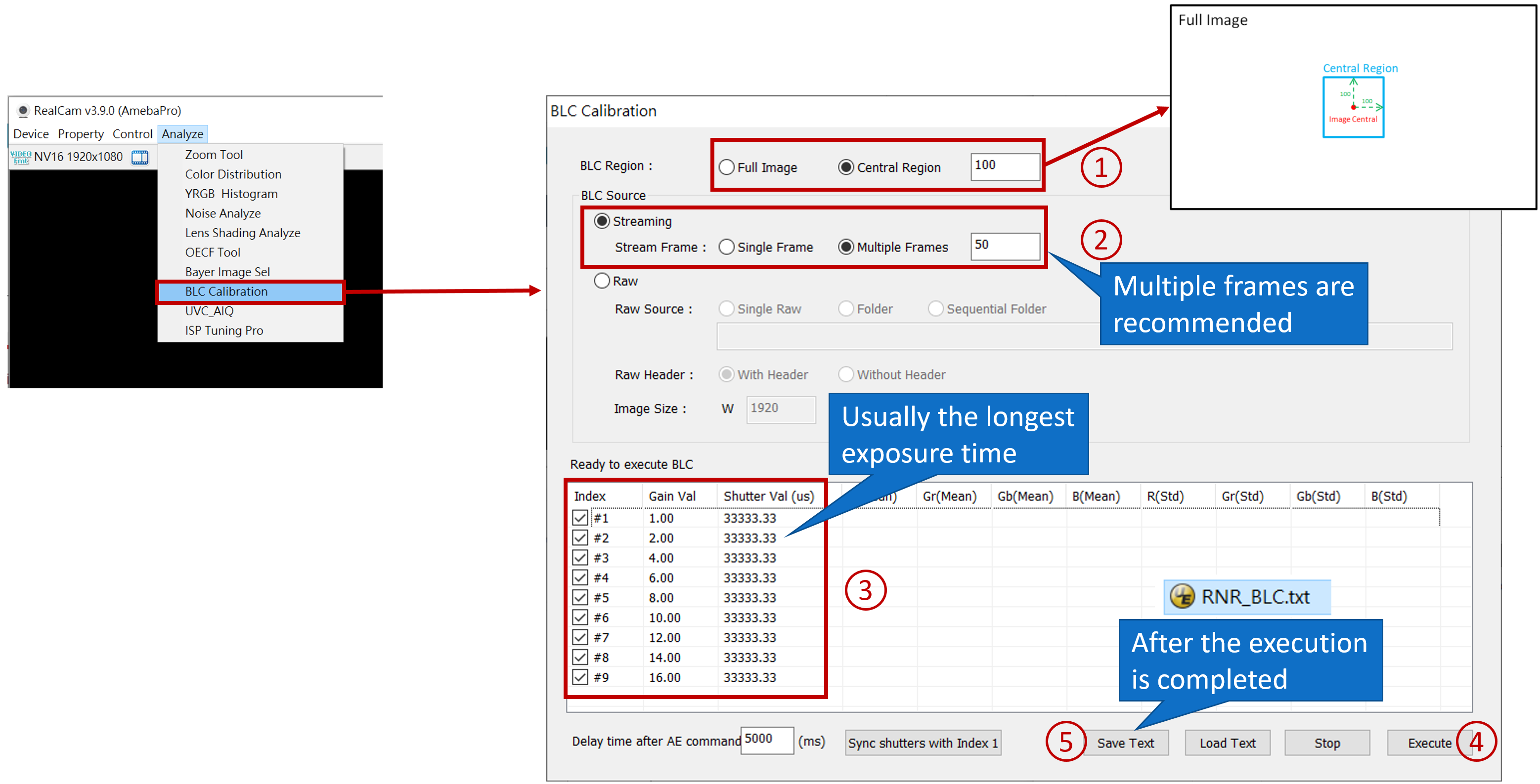
BLC calibration
BLC IQ set
LSC calibration
AWB calibration
CCM calibration
Basic Calibration Module_BLC calibration
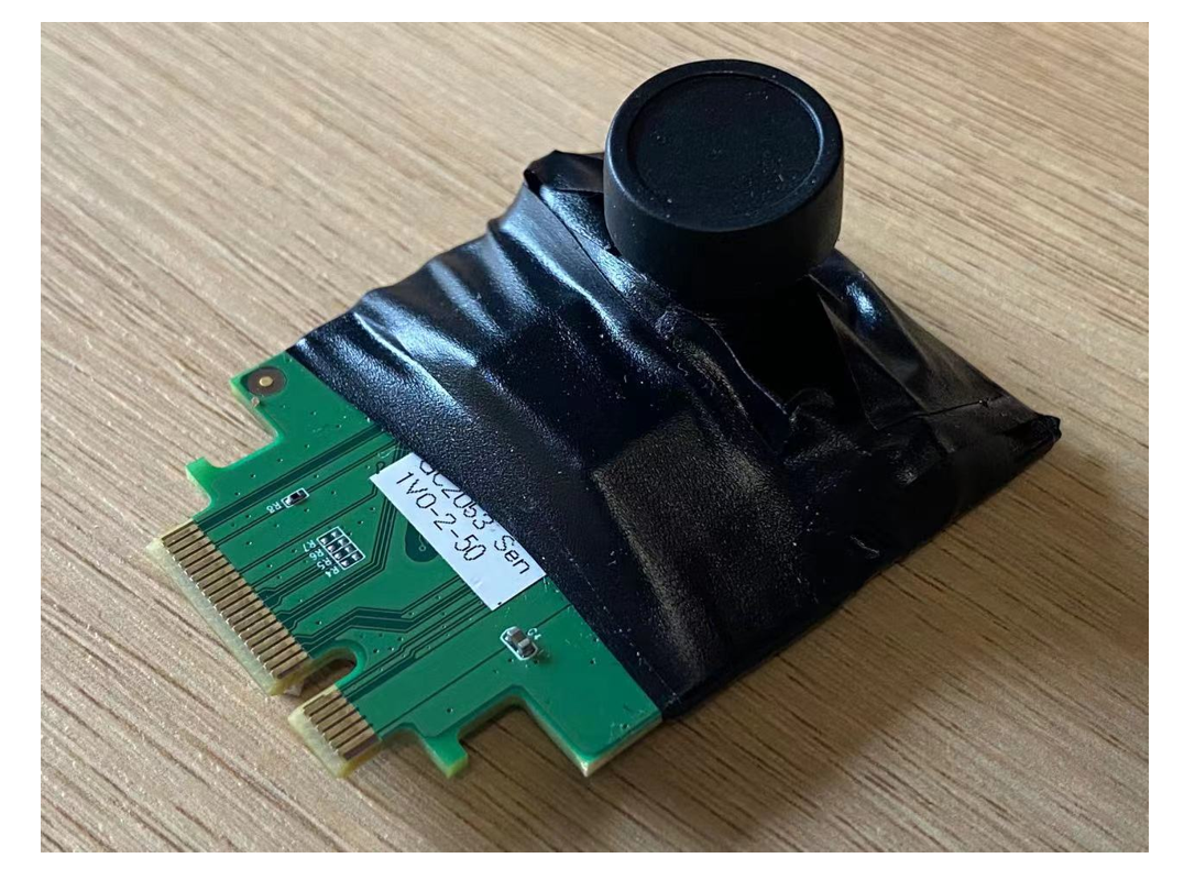
BLC calibration
Make sure the lens module is light-tight. Cover the lens to block out light. Use a lens cap or opaque black cloth, and place it in a light-free environment. If it’s a sensor PCB board, it’s suggested to use black tape to stick onto the backplate and prevent light leakage.
Basic Calibration Module_BLC calibration
Basic Calibration Module_Fast BLC IQ set
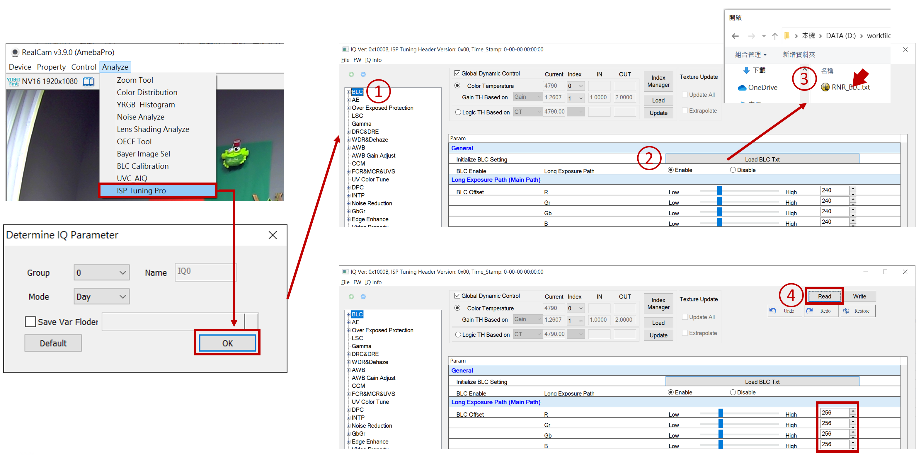
Basic Calibration Module_Fast BLC IQ set
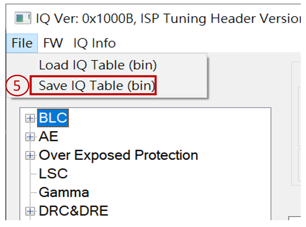
Once saved as a bin file, the BLC settings are completed. You can load the bin file to check if it matches the set parameters.
Basic Calibration Module_Manual BLC IQ set

Need to uncheck Global Dynamic Control first
Basic Calibration Module_Manual BLC IQ set
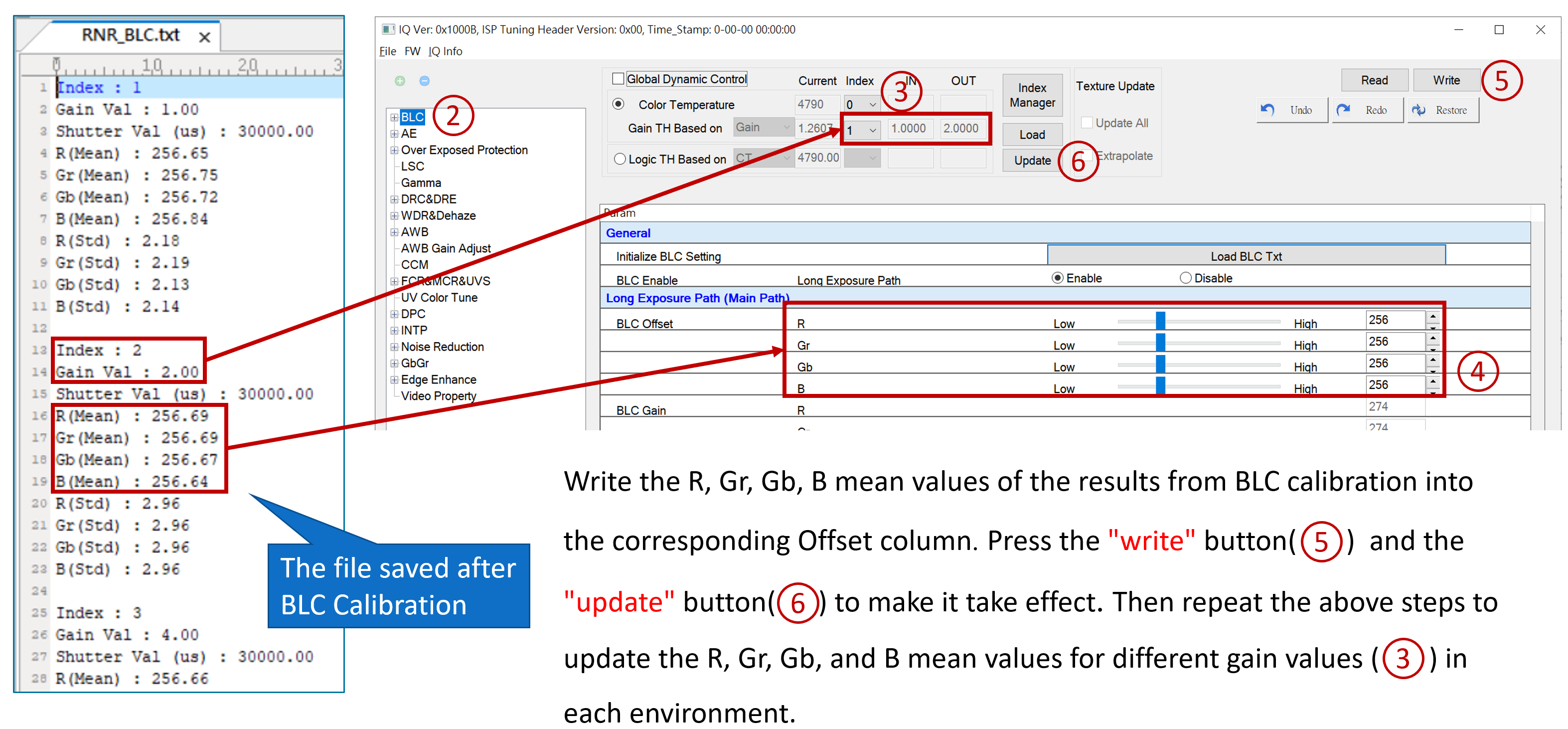
Basic Calibration Module_Manual BLC IQ set
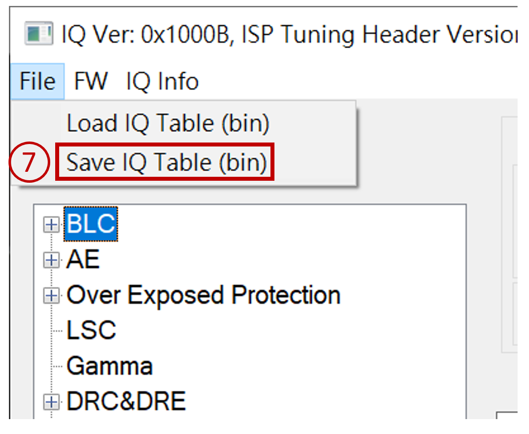
Once saved as a bin file, the BLC settings are completed. You can load the bin file to check if it matches the set parameters.
Basic Calibration Module_LSC calibration
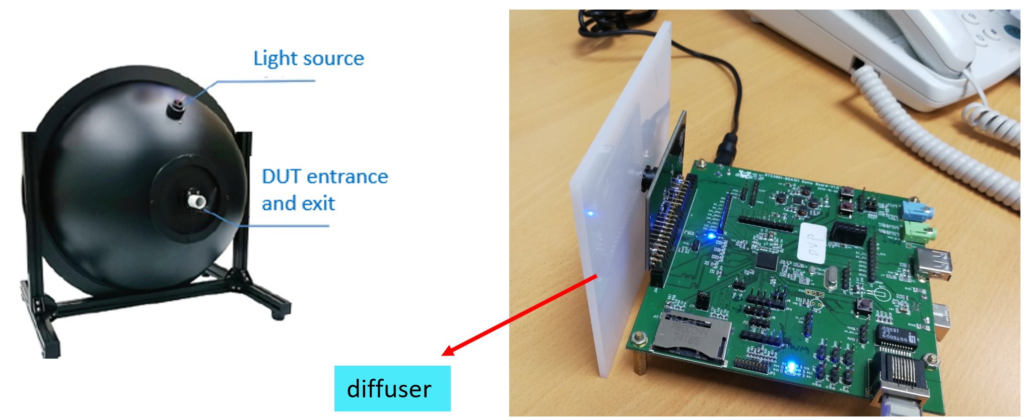
To calibrate LSC, use integral sphere, DNP lightbox, optical diffuser, or milky acrylic panel as a diffuser to cover the lens and align with the light source in a uniform environment. The purpose is to ensure the uniform. The recommended light source color temperature is D65 or D50.
Basic Calibration Module_LSC calibration
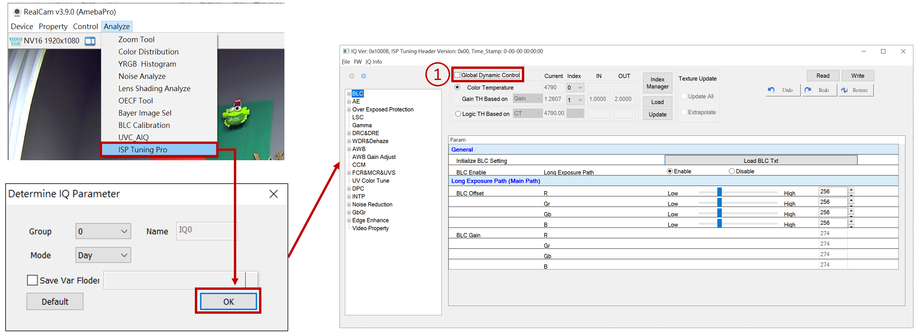
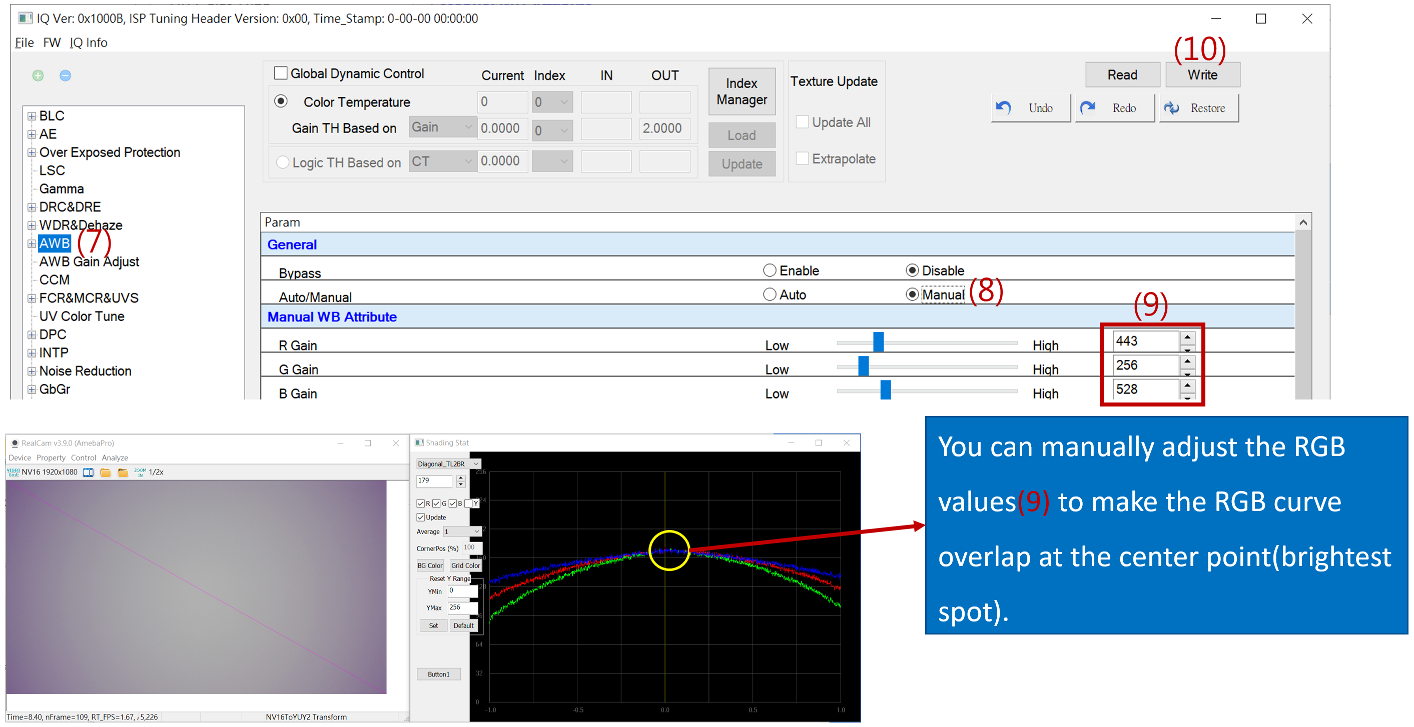
Need to uncheck Global Dynamic Control first
Basic Calibration Module_LSC calibration
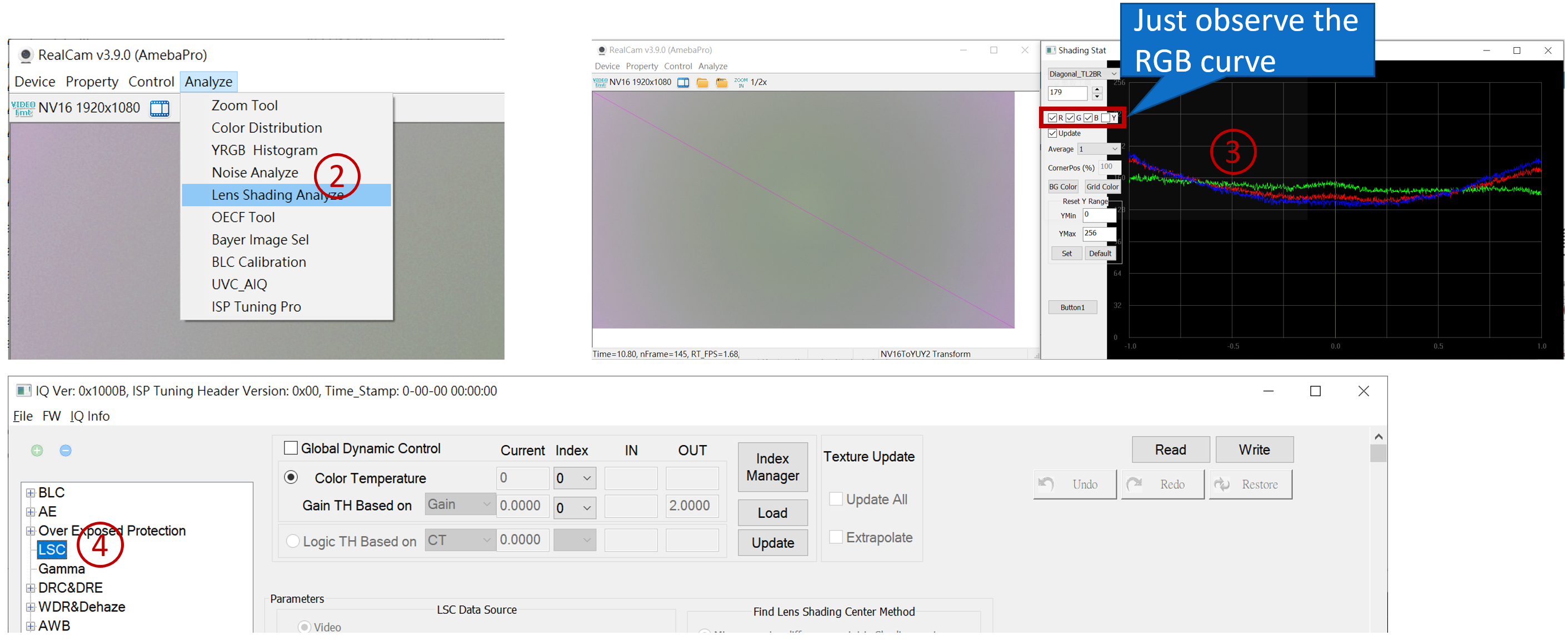
Turn on Lens Shading Analyze to observe. The better the RGB curve overlap, the better the color cast correction.
Basic Calibration Module_LSC calibration
Basic Calibration Module_LSC calibration
Basic Calibration Module_LSC calibration
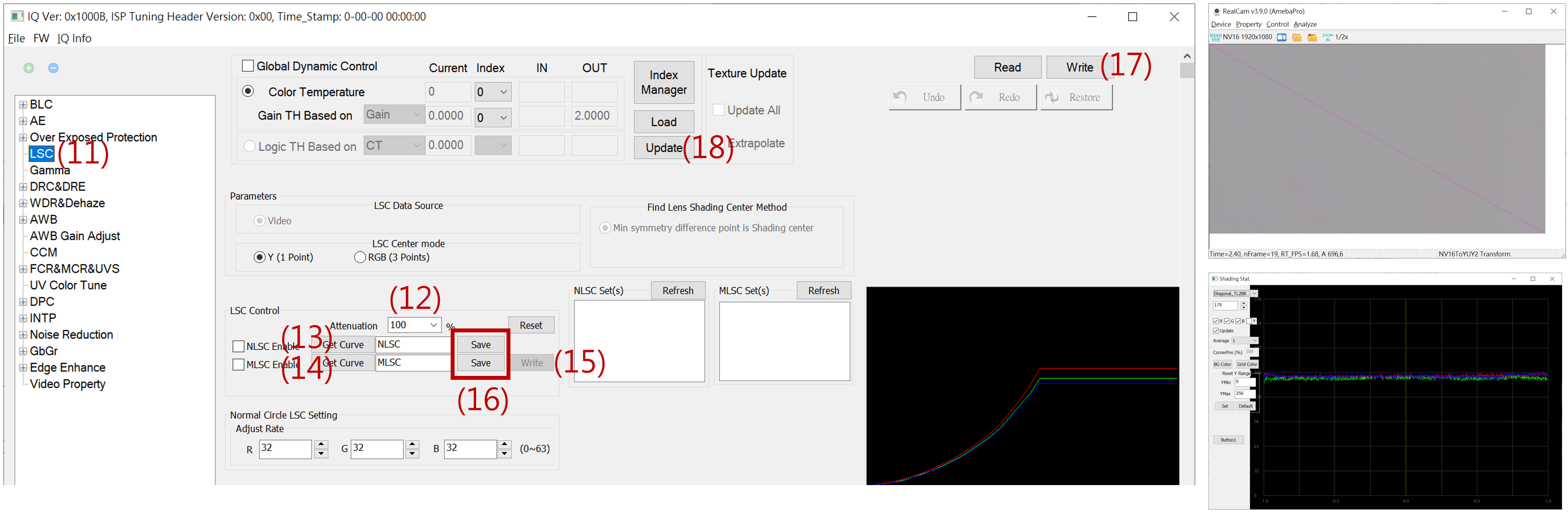
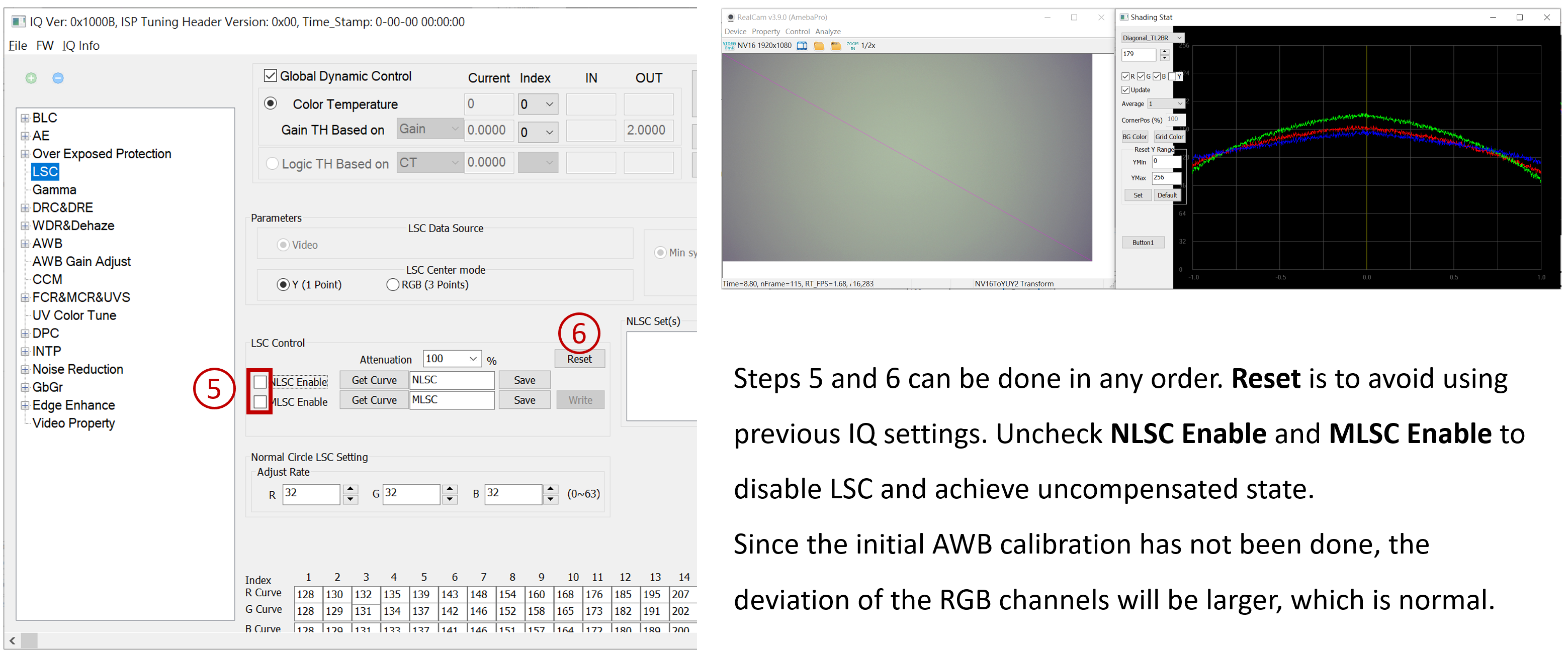
Attenuation:The degree of correction for Lens Shading. If set to 100%, it means that the brightness around the image after correction will be the same as the center brightness. To suppress noise at the corners, it is recommended to choose an Attenuation of 70% to 90%.
NLSC 【Get Curve】MLSC 【Get Curve】: If the lens quality is good, just do NLSC calibration.
Basic Calibration Module_LSC calibration
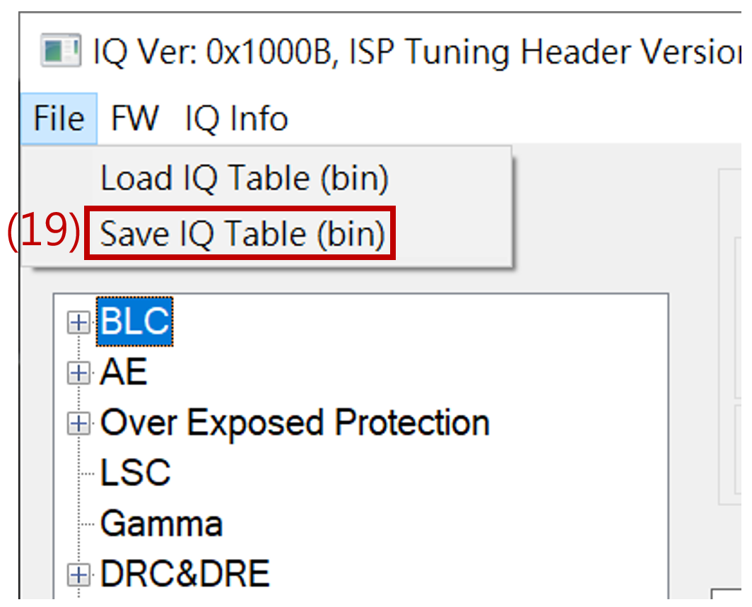
Once saved as a bin file, the LSC settings are completed. You can load the bin file to check if it matches the set parameters.
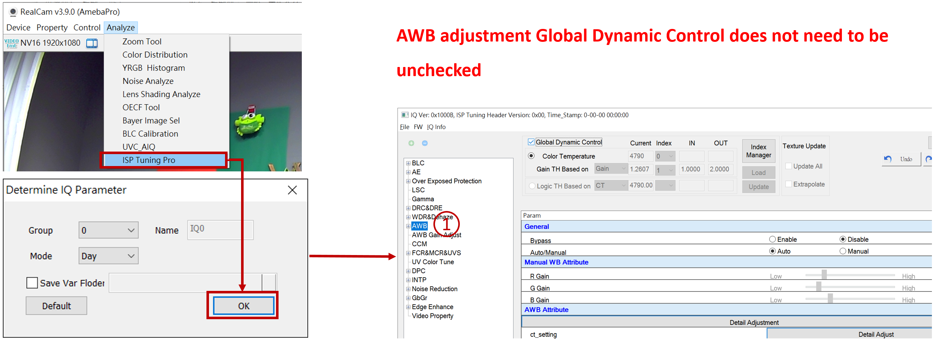
AWB calibration
It is recommended to prepare a multi-color temperature lightbox and a gray card (gray points will be concentrated in one place) for AWB calibration. The suggested calibration color temperature is as follows: D75、D65 、D50 、CWF 、U35 、A(U30)
Because the image presented by realcam is the result of the final image processing, it is recommended
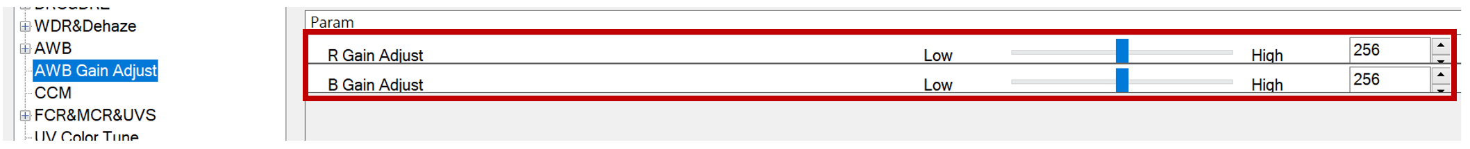
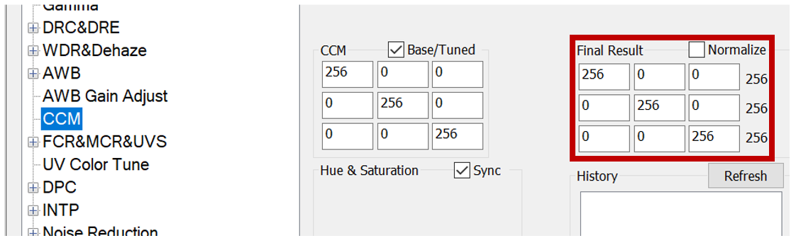
Do not multiply R and B gains in AWB Gain Adjust, keep it at the default value of 256 (1x).
Set CCM to the unit matrix.
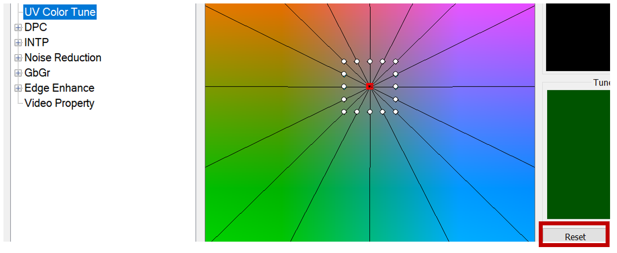
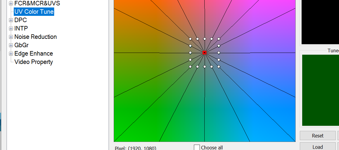
Reset any UV effects to default.
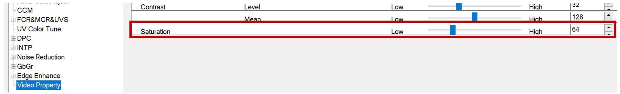
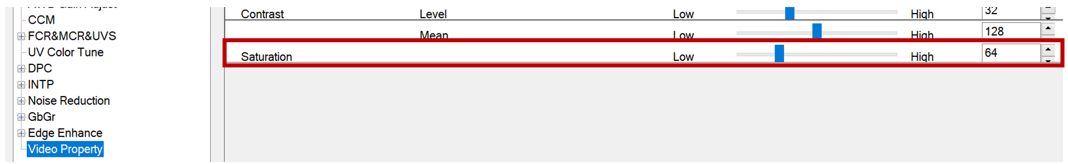
In Video property, set saturation to 64(1x)
Tip
In the above functions, make sure to uncheck Global Dynamic Control first before making modifications. To change to default values, press “write” and “update” (must be done before switching to the function page). Save it as a bin file to avoid redoing in case of a system crash.
AWB calibration
Do not add R B gain in AWB gain Adjust, the default is 256 (1x)
Set the CCM as the identity matrix
UV color tune set back to default
In the Video property, set the saturation to 64 (1x)
AWB calibration
After confirming the above parameters, you can load the saved bin file and check the Global Dynamic Control mode to begin AWB calibration.
AWB calibration
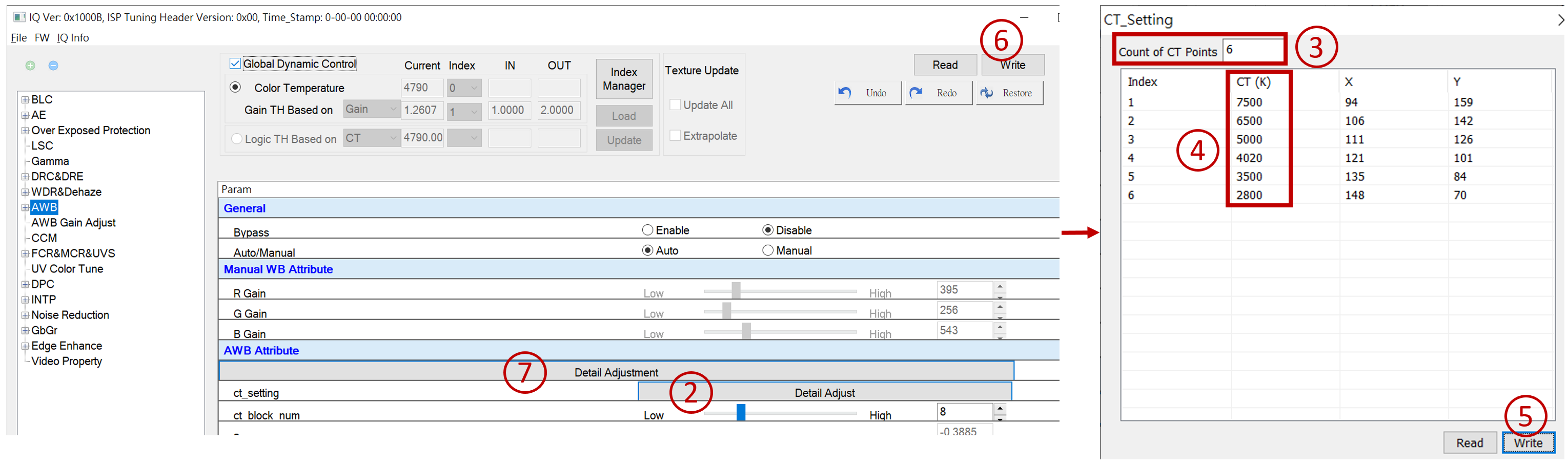
Decide how many sets of light sources need to be calibrated, and modify the Count of CT Points column in the ct_setting window.
Switch the lightbox switch to the light source that needs calibration, modify the CT (K) field value in the ct_setting window to match the color temperature value of the light source.
AWB calibration
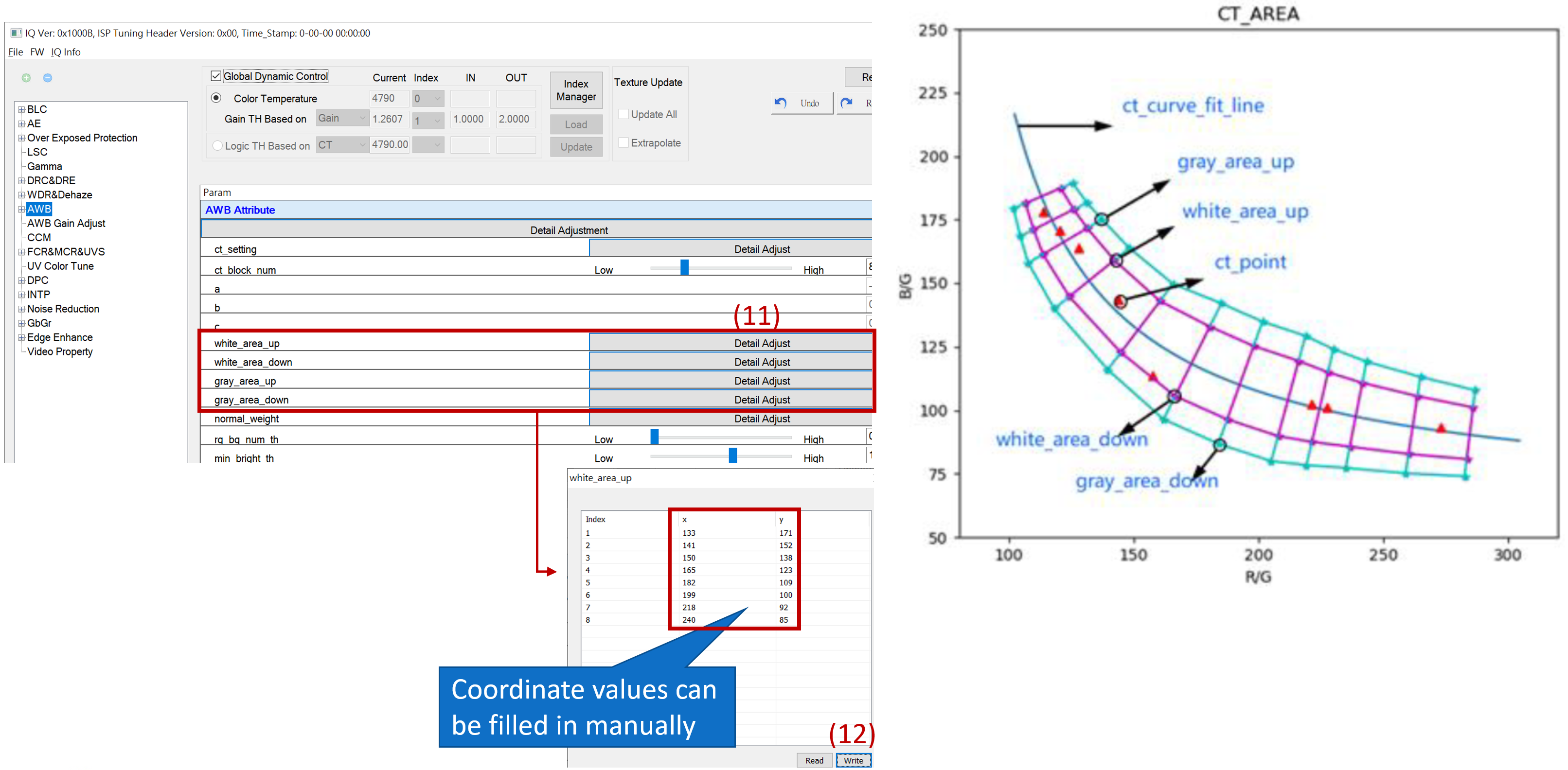
You can modify the X/Y coordinate values in the ct_setting window or utilize the real-time display of the mouse cursor position in the lower left corner of the AWB Analyze window to obtain the coordinates of the current red dot and fill them in as reference values.
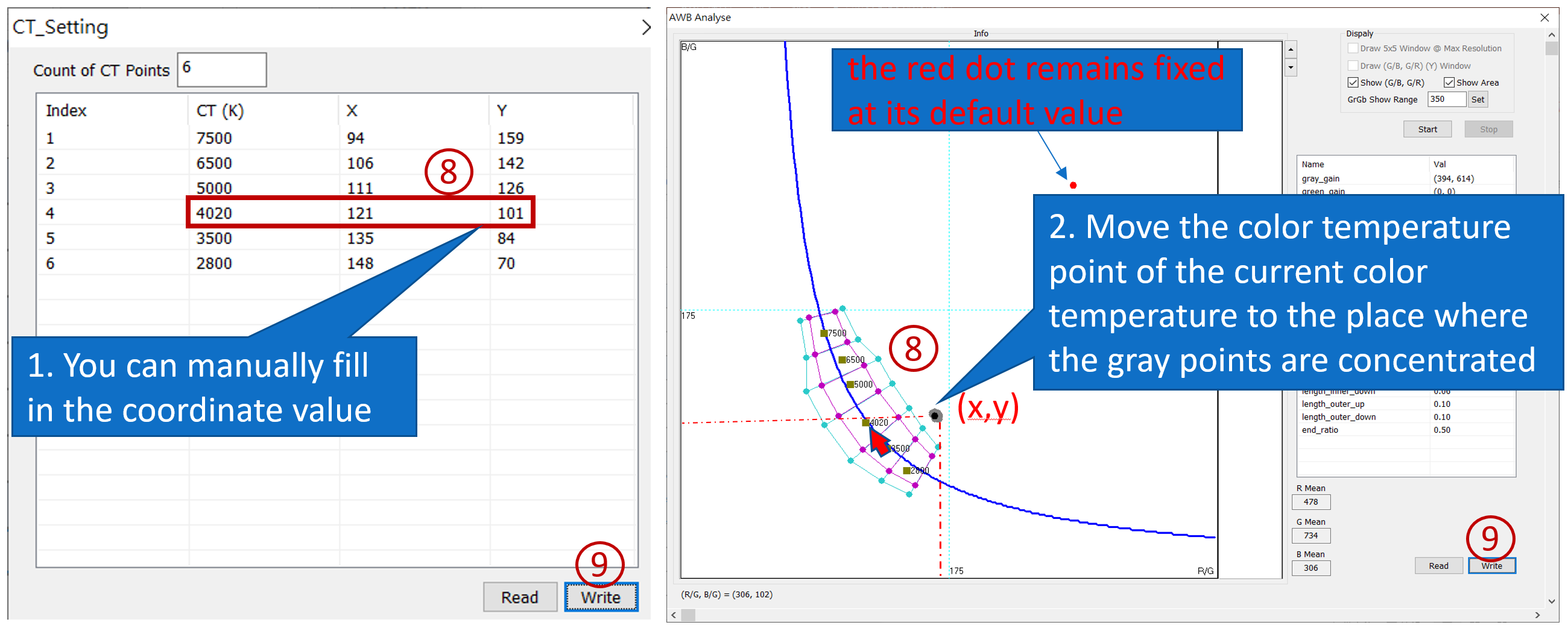
Ex: color temperature 4020k(In this case, all the gray dots are outside the white and gray areas, and the red dot remains fixed at its default value. So, you can start by moving the color temperature point to the place where the gray points are concentrated.Once the red dot is in a normal position, you can make fine adjustments.)
AWB calibration
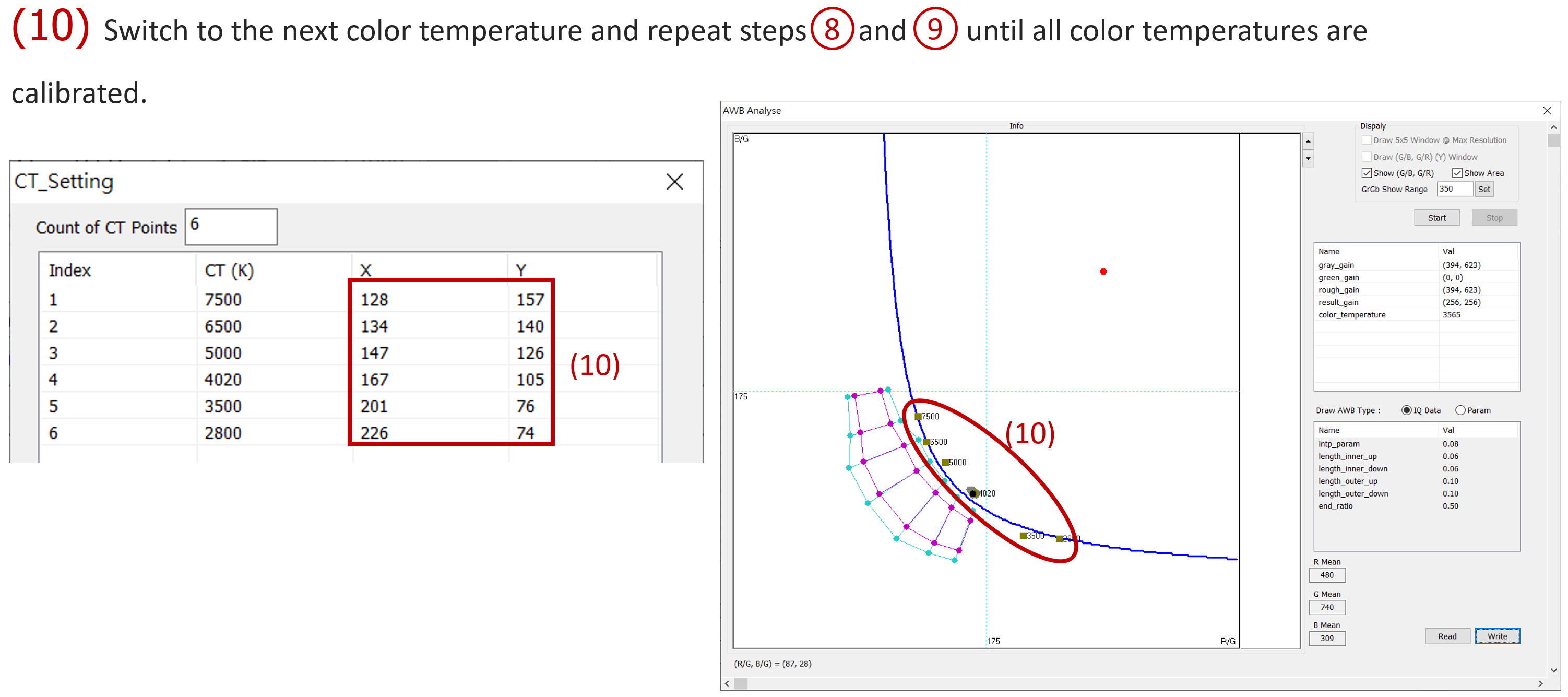
AWB calibration
Switching to Param will automatically calculate the white area (pink) and gray area (blue) area, and it can also be modified manually (next page)
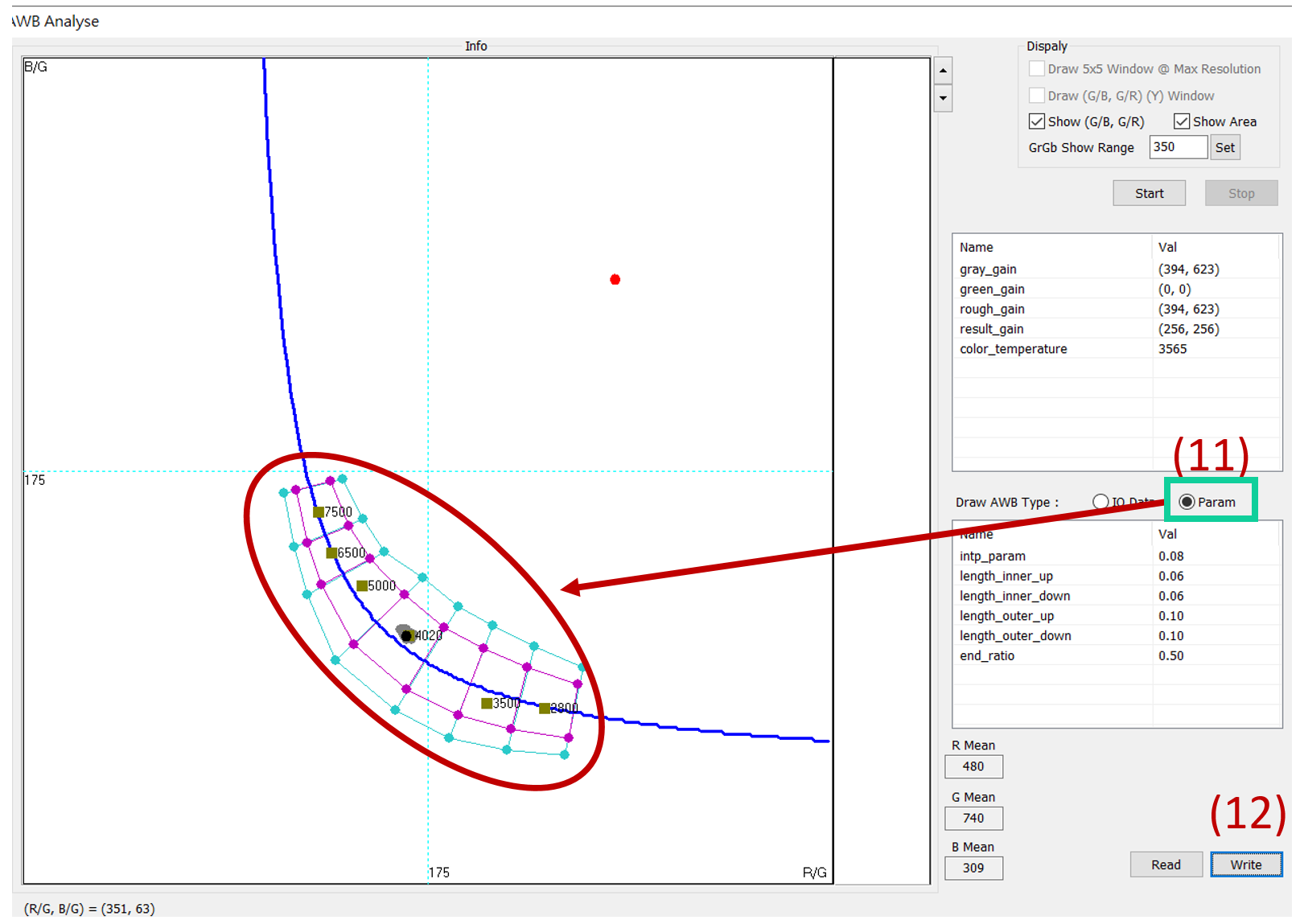
AWB calibration
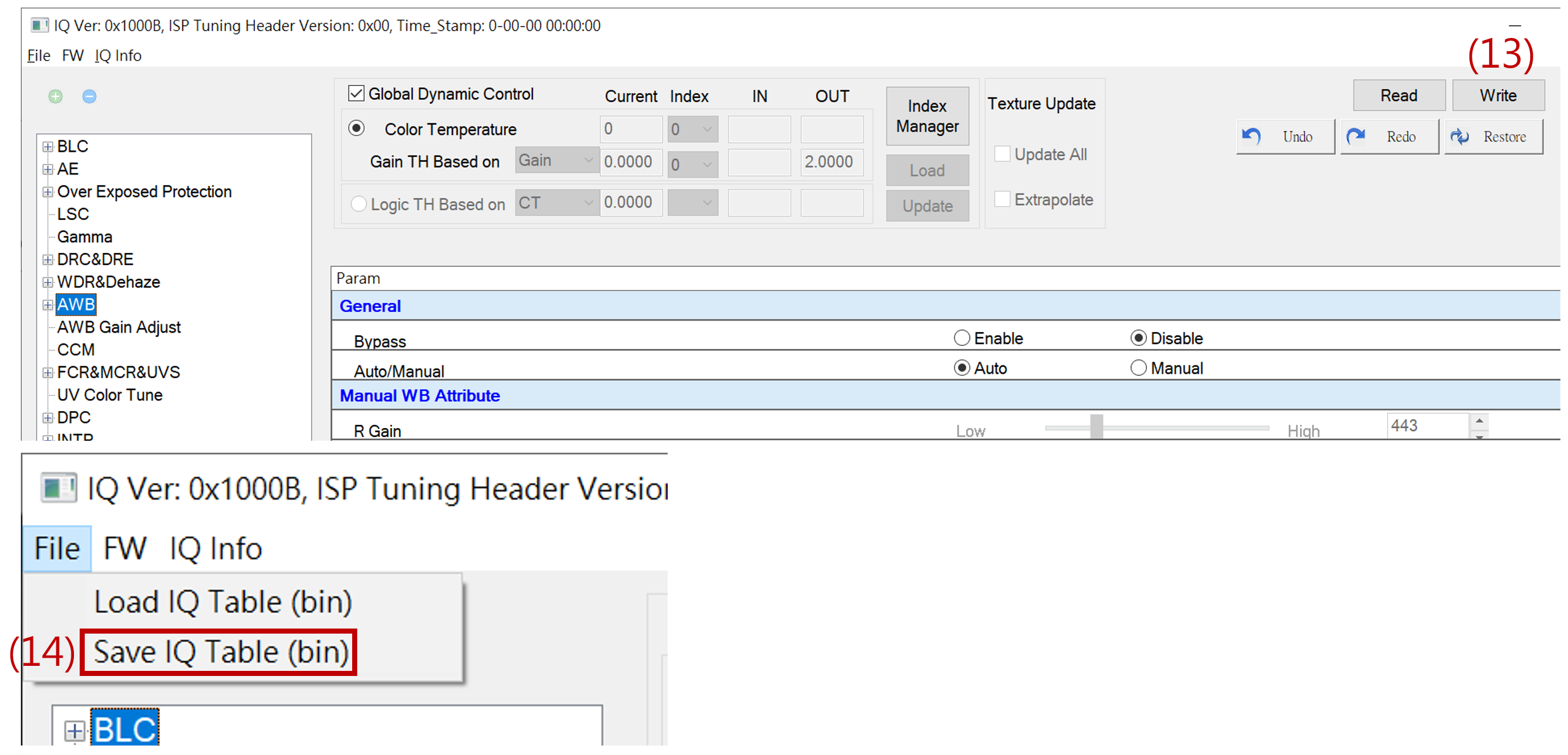
AWB calibration
Once saved as a bin file, the AWB settings are completed. You can load the bin file to check if it matches the set parameters.
CCM calibration
Prepare multi-color temperature light boxes and 24 color charts, and do CCM calibration.
Because the image presented by realcam is the result of the final image processing, it is recommended
UV color tune set back to default
In the Video property, set the saturation to 64 (1x)
Tip : In the above functions, make sure to uncheck Global Dynamic Control first before making modifications. To change to default values, press “write” and “update” (must be done before switching to the function page). Save it as a bin file to avoid redoing in case of a system crash.
CCM calibration
UV color tune set back to default
In the Video property, set the saturation to 64 (1x)
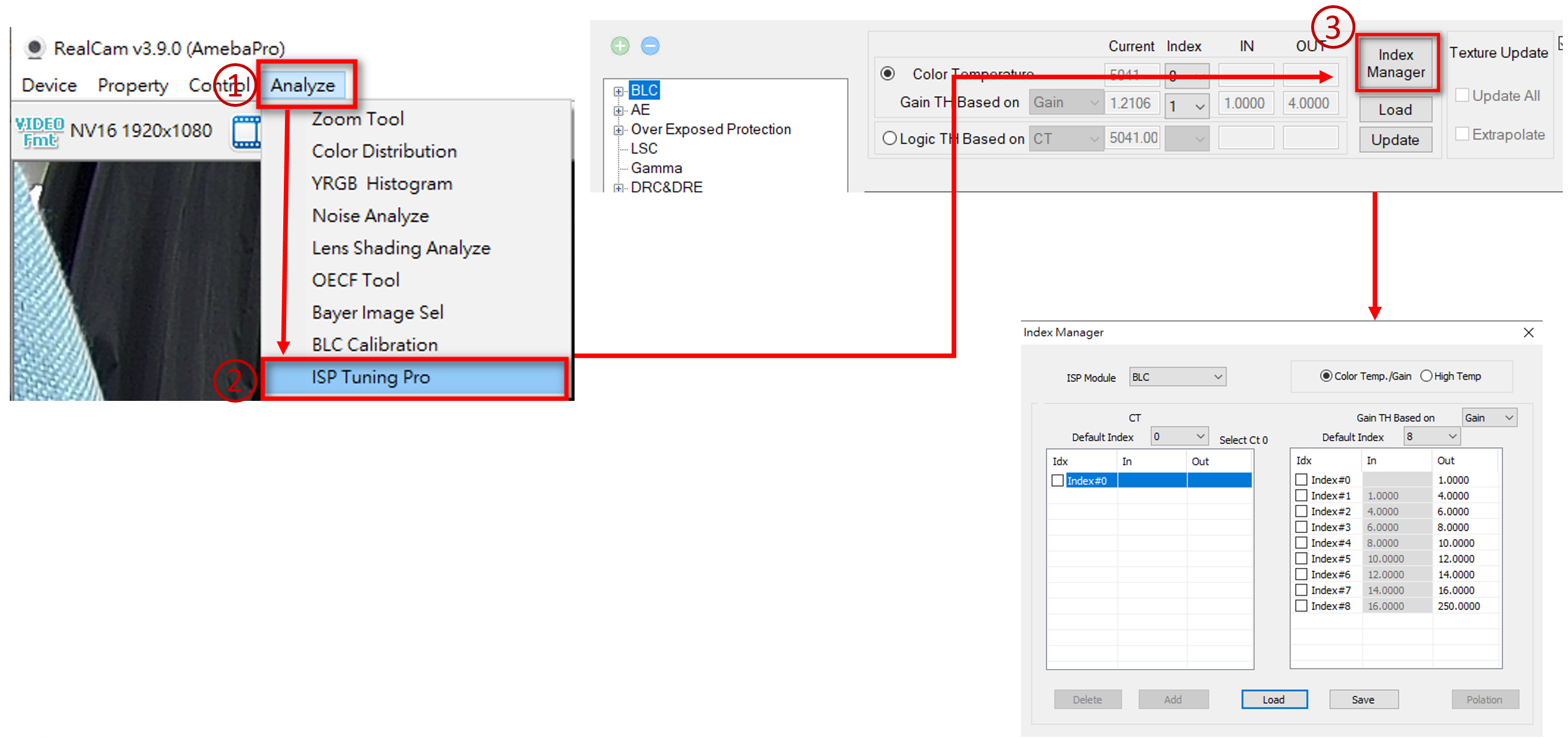
CCM calibration
Determine the number of calibration light sources and modify the CCM column in the Index Manager window.
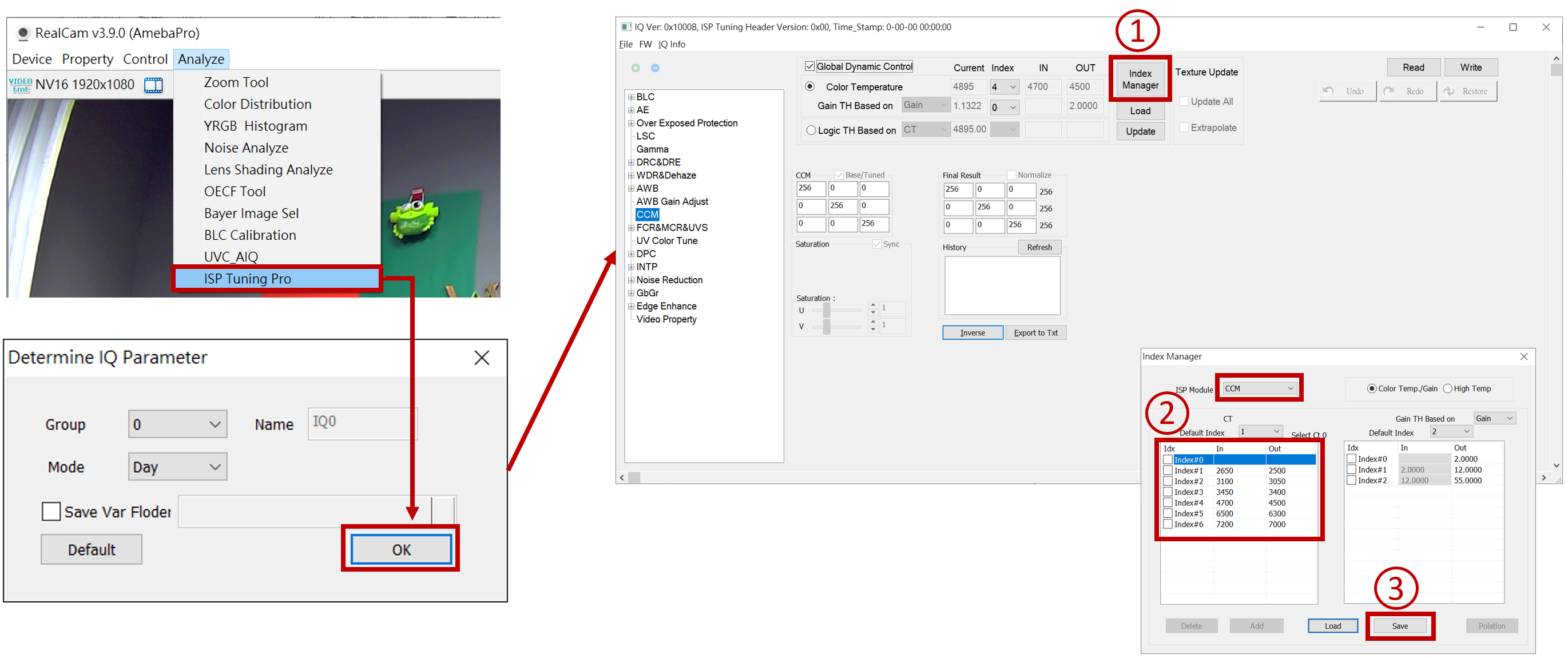
CCM calibration
Place the Color Checker in the light box, select the color temperature light source to be corrected, and uncheck Global Dynamic Control first.
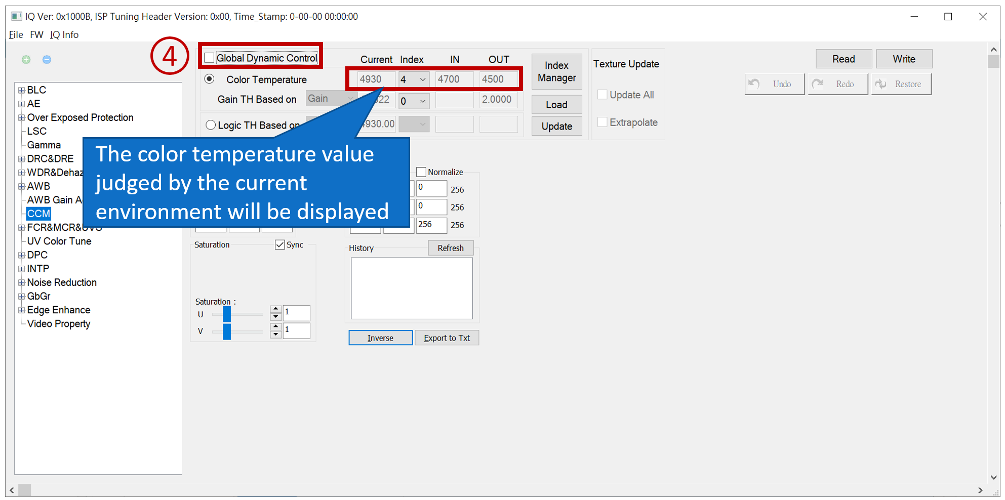
CCM calibration
UVC_AIQ 🡪 UvcAIQ_Init 🡪 Set Patch Position
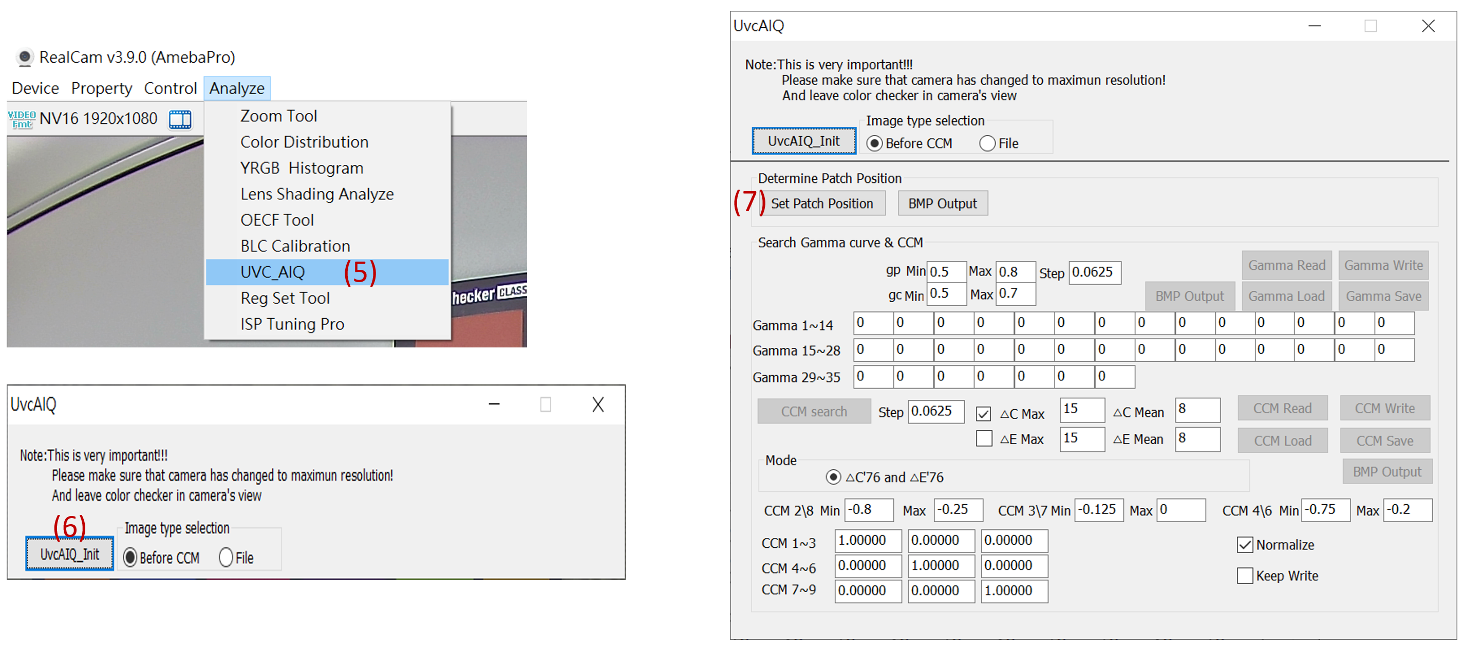
CCM calibration
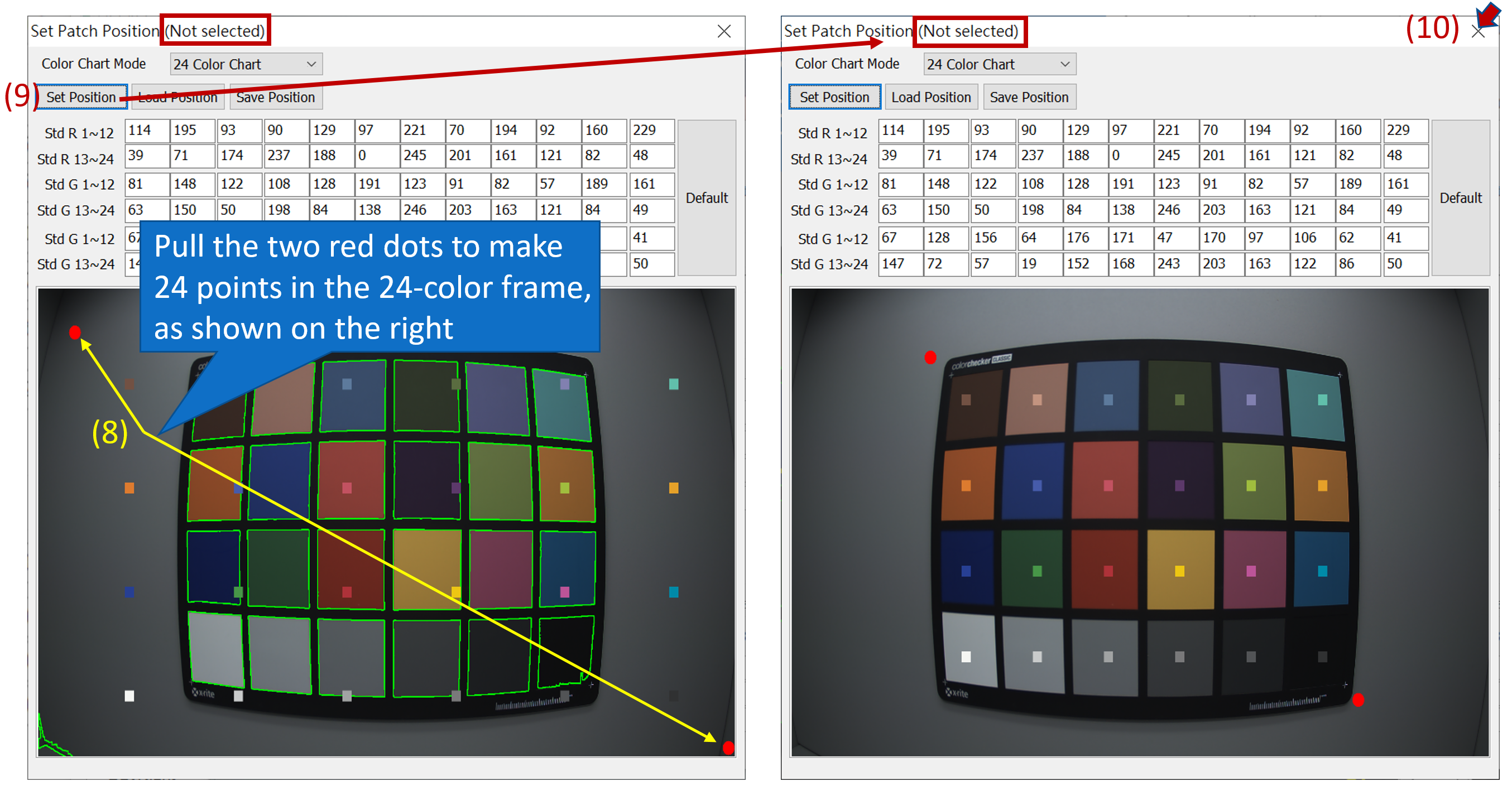
CCM calibration
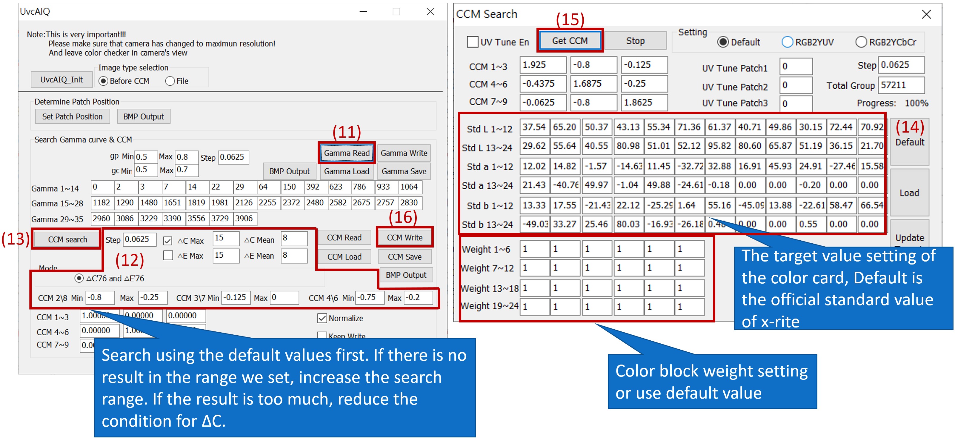
CCM calibration
Read the CCM value calibrated by AIQ, and after updating, the CCM calibration of this color temperature will be completed.
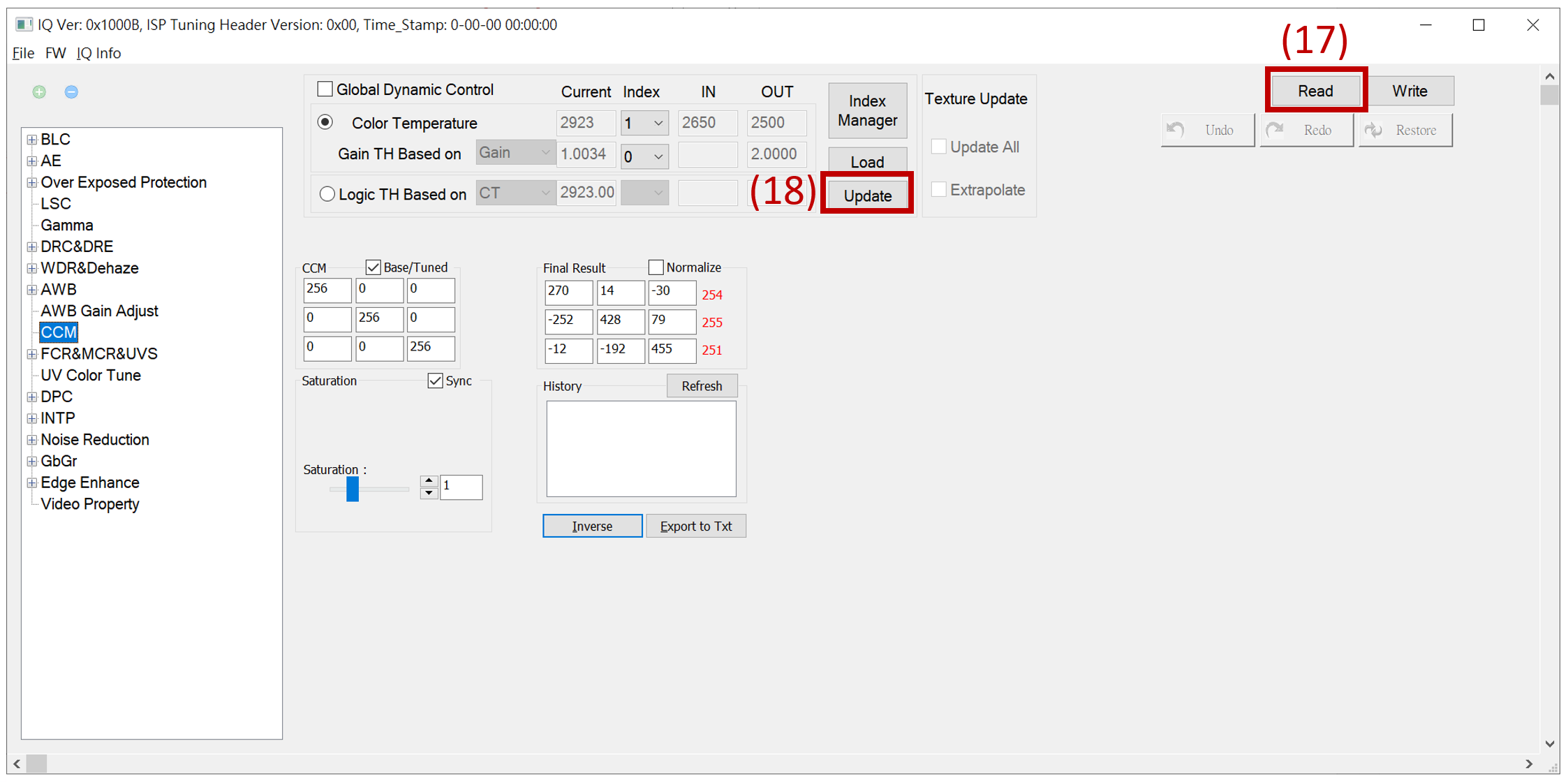
CCM calibration
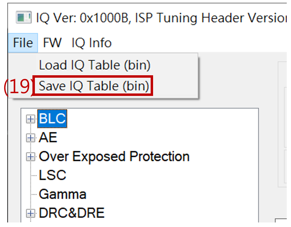
Once saved as a bin file, the CCM settings are completed. You can load the bin file to check if it matches the set parameters.
Load bin file and check the Global Dynamic Control mode , switch to the next color temperature light source, and get the next Index color temperature value, repeat the above steps, and calibrate the CCM of each color temperature once.
Added IQ parameter range
Purpose: When a certain scene needs to be adjusted accurately, the color temperature and gain range can be added for this scene, and the parameters between other scenes will be formed by static switching and dynamic interpolation.
category:
Add color temperature range
Add exposure ratio range
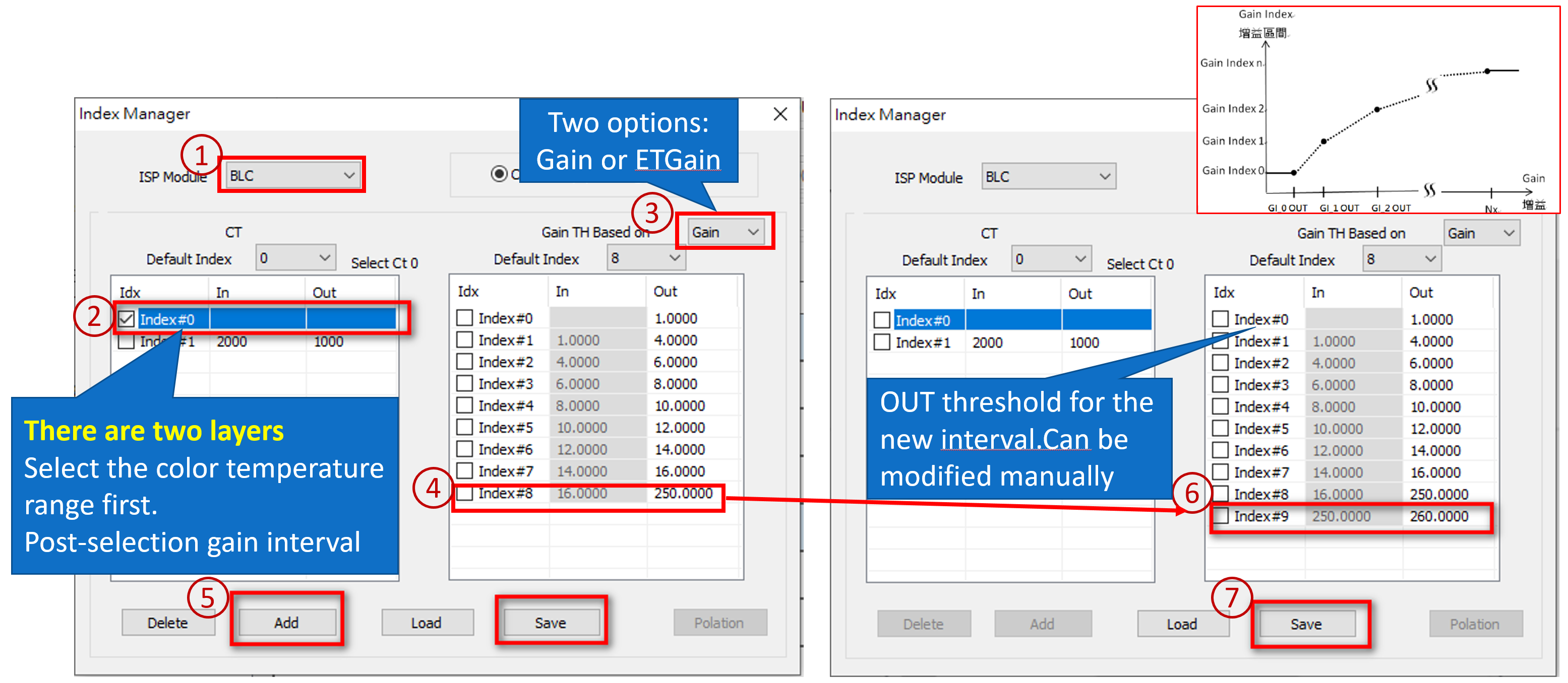
New gain range
Added IQ parameter range
Operation method:
Add color temperature range
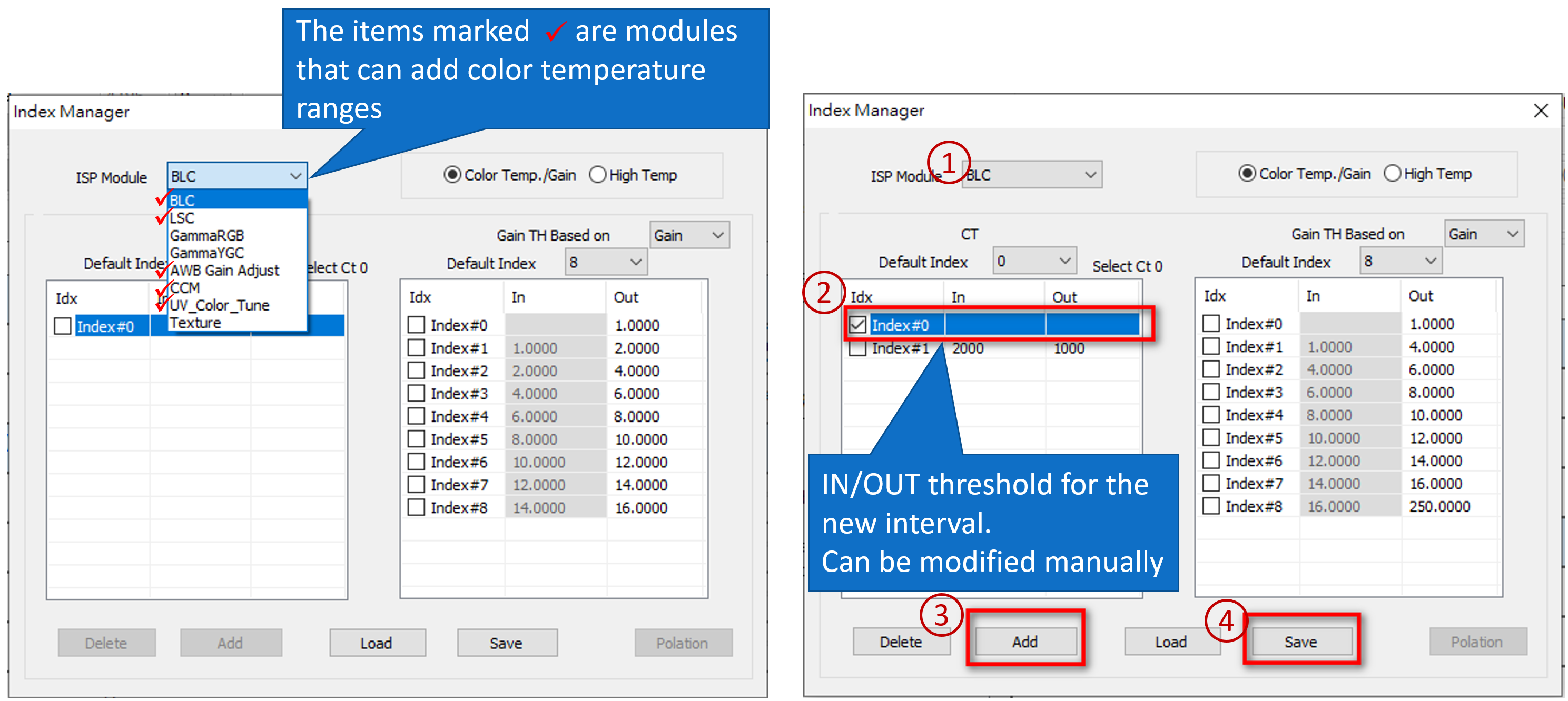
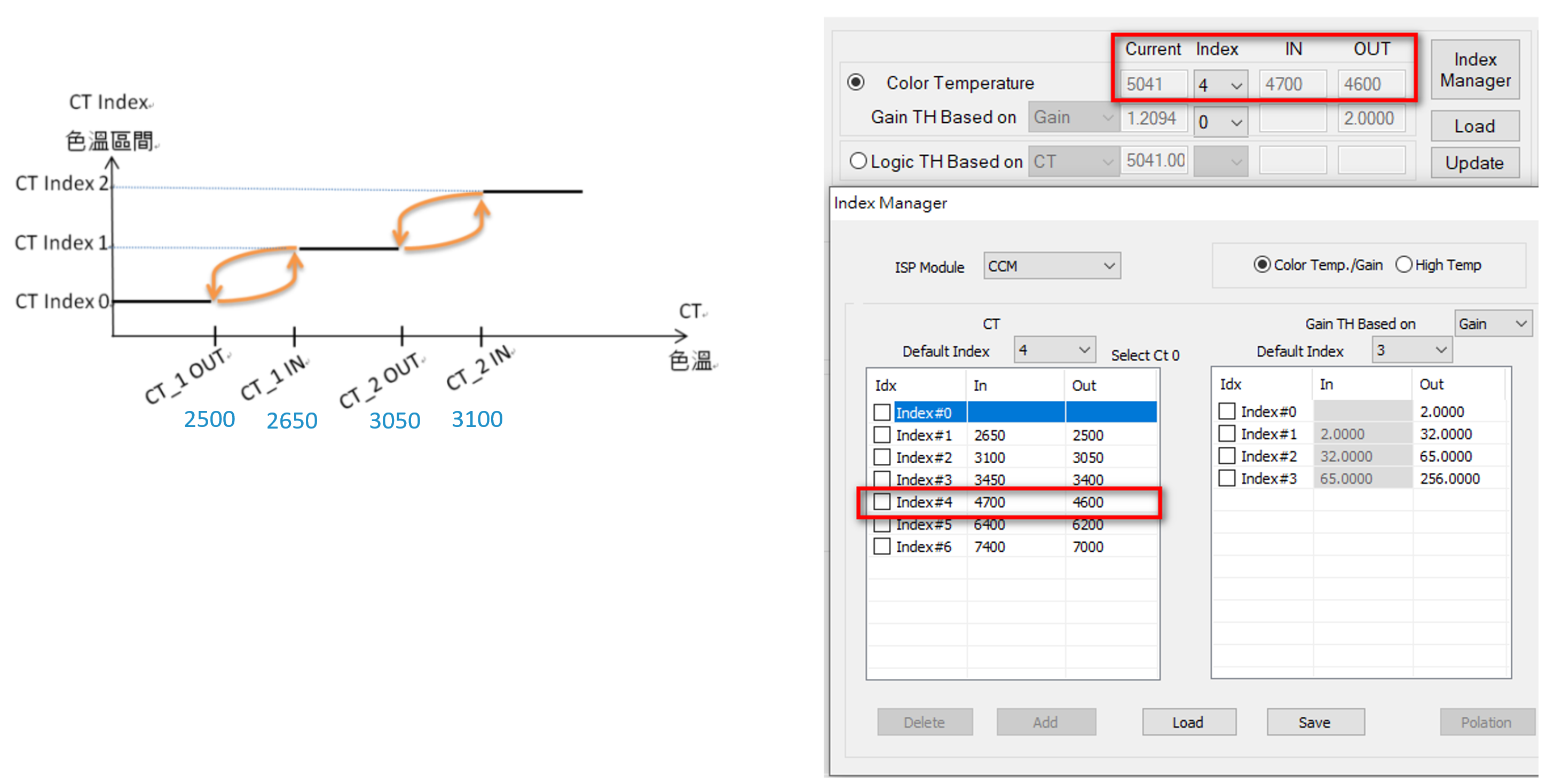
Added color temperature range - color temperature threshold
IN: Displays the threshold value of entering the color temperature range (color temperature up)
OUT: Displays the threshold value for leaving the color temperature range (color temperature descending)
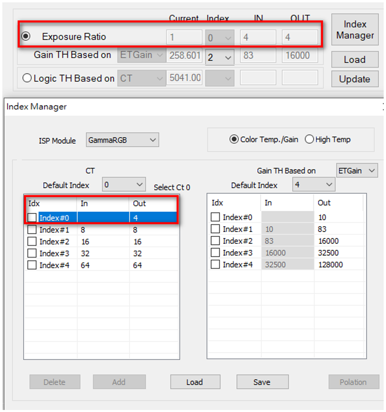
Add exposure ratio range
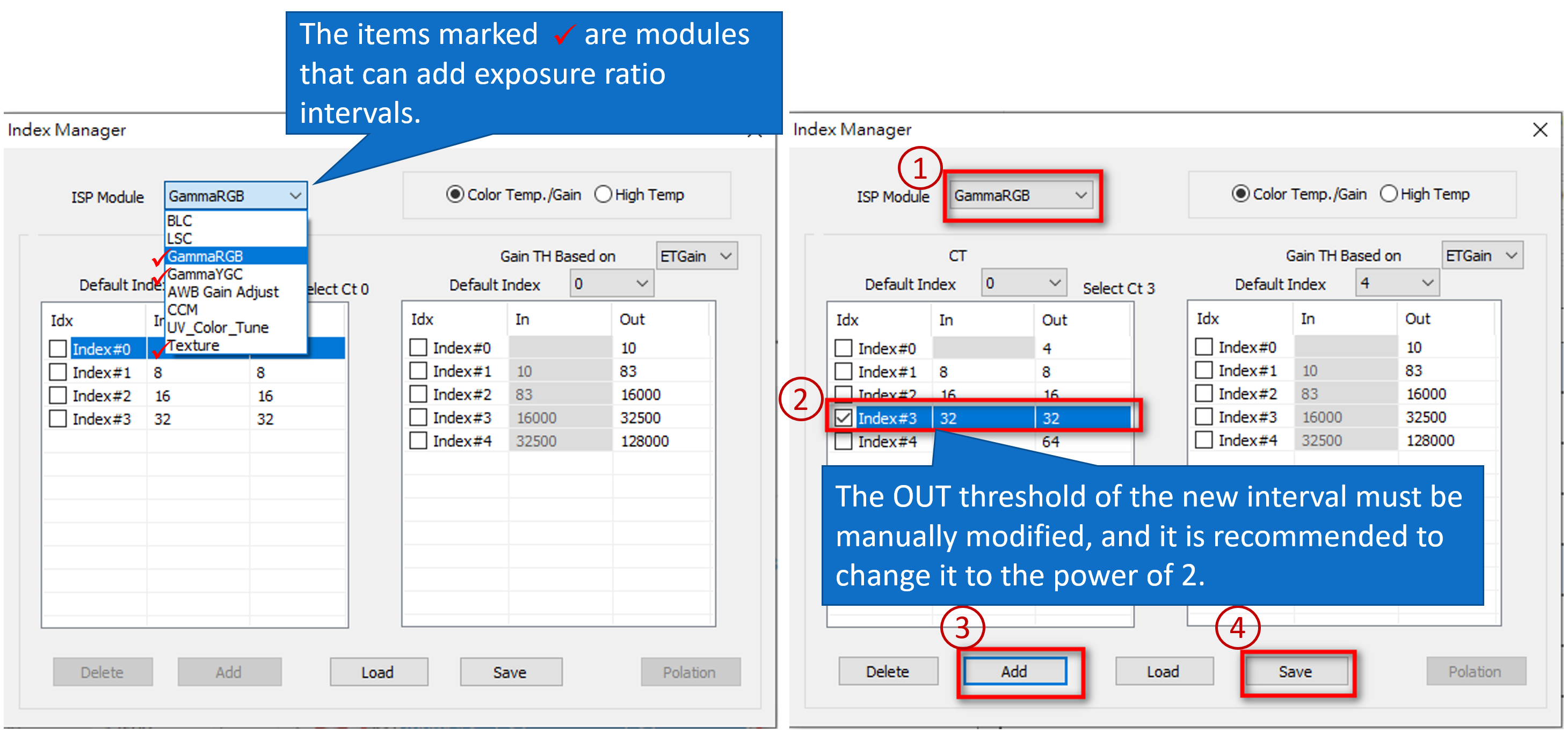
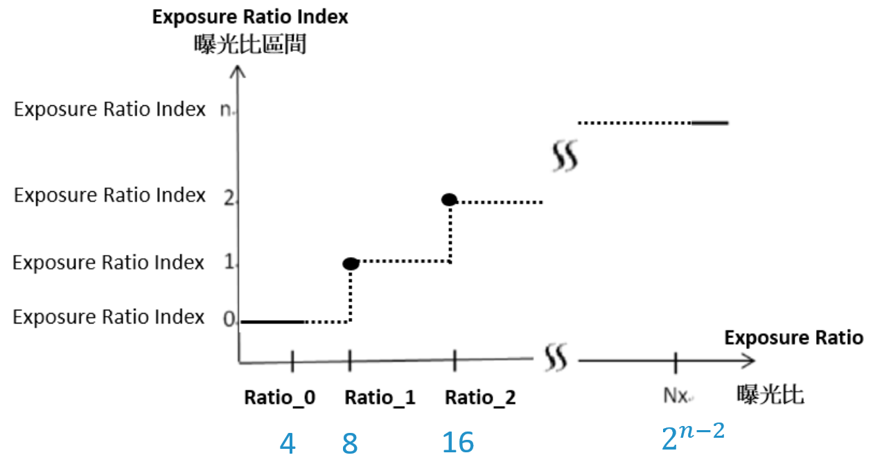
Added exposure ratio interval-exposure ratio threshold
vHDR sensor will start.
Magnification is 2^𝑛: 2, 4, 8, 16, 32, 64.
If the exposure ratio falls between the two sets of Indexes, the parameters of the previous set of indexes will be maintained.
New gain range