Image sensor
For Mipi sensor application, please refer below.
GPIOE_0 –> sensor_RSTB
SEN_PDN –> sensor_PDN
GPIOA_5 –> sensor_PWR_EN
SEN_SCL –> I2C_SCL
SEN_SDA –> I2C_SDA
SEN_SYSCLK –> sensor clock
Pull high I2C by 4.7k ohms
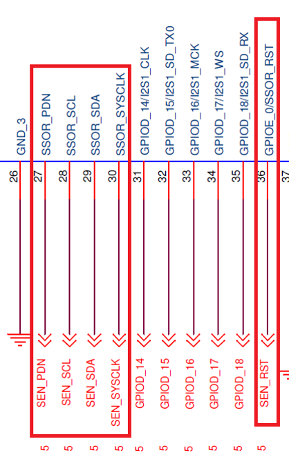
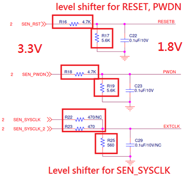
Image sensor level shifter
For 1.8V sensor IO level shifter, please refer below.
Sen_RSTB –> use 4.7k, 5.6K ohms
Sen_PDN –> use 4.7k, 5.6K ohms
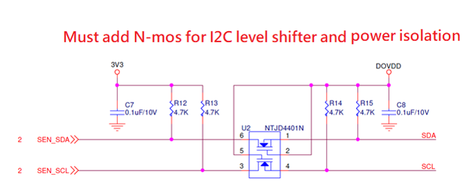
SEN_SCL –> I2C_SCL NTJD4401N/SM1600DSCS, PH 4.7k ohms
SEN_SDA –> I2C_SDA NTJD4401N/SM1600DSCS, PH 4.7k ohms
SEN_SYSCLK –> use 470, 560 ohms
Note
The 1.2V and 1.8V power rails can be generated from LDOs powered either by VDD33 or V_USB.
If powered by V_USB, the available current may be limited (e.g., 24%–36% of rated capacity) and may cause overheating.
If powered from the VDD33 rail shared with the AmebaPro2 SoC, power noise may propagate and affect sensitive modules.
To ensure stable operation of camera sensor modules, it is recommended to use a dedicated DC-DC buck converter for the camera power domain. It is also recommended to consult the camera sensor module manufacturer for their suggested LDO design and recommended components.
Refer to VDD33 for details on power noise. Refer to DC BUCK for DC-DC buck design guidelines.